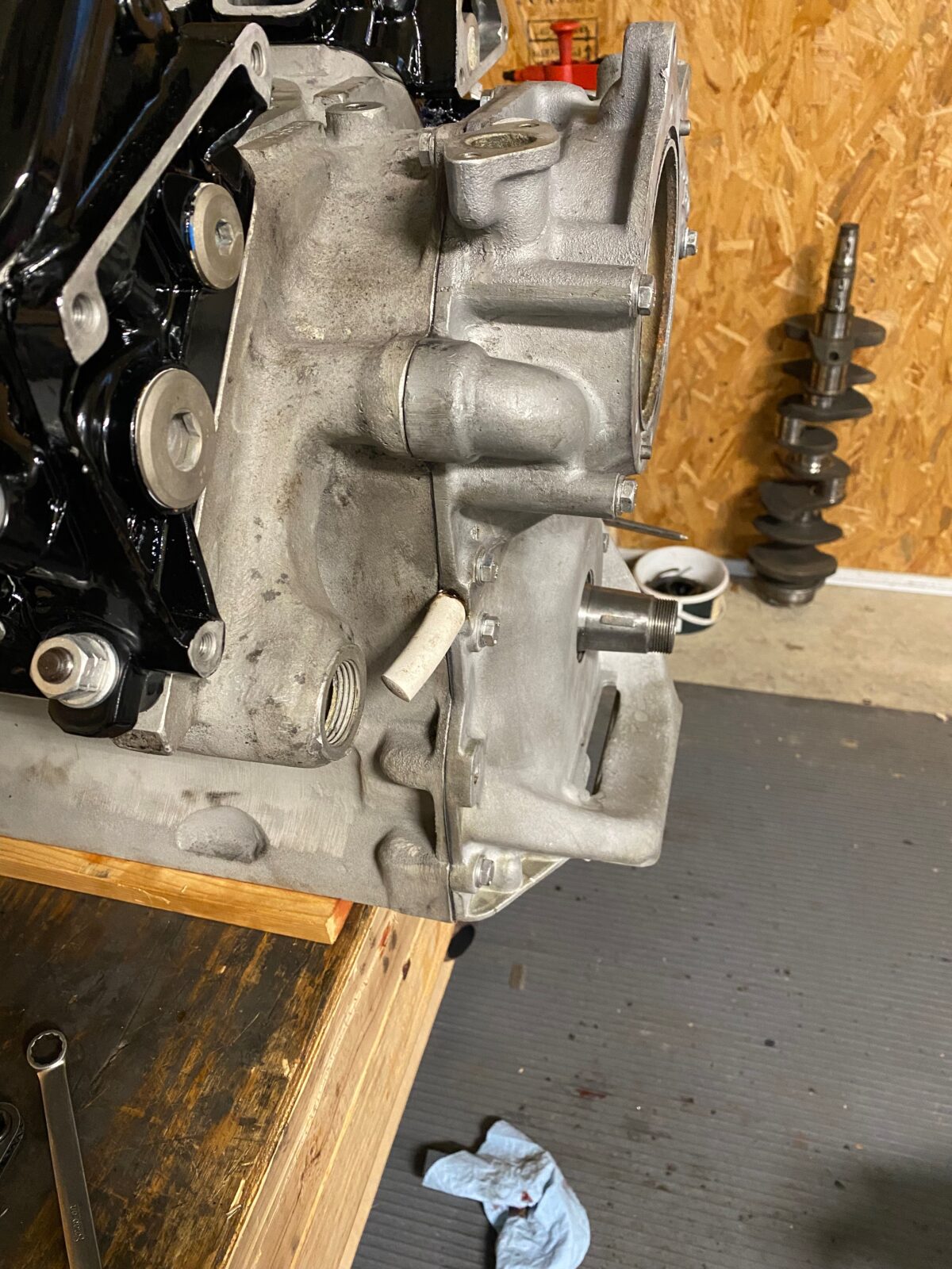
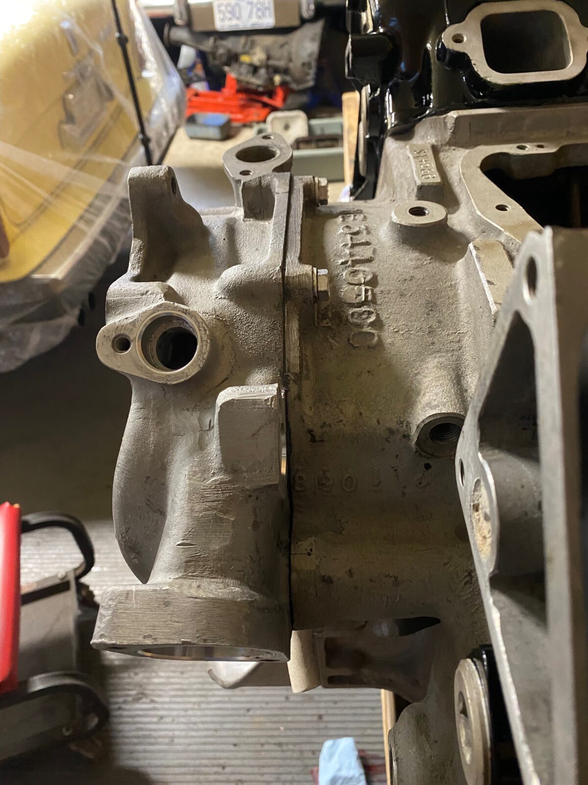
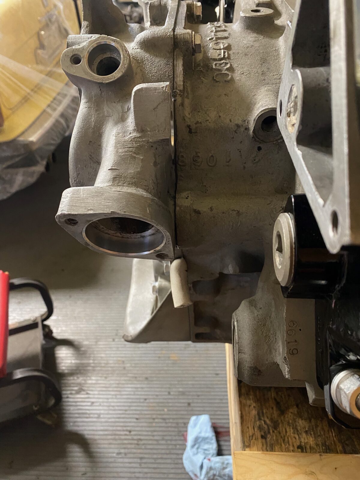
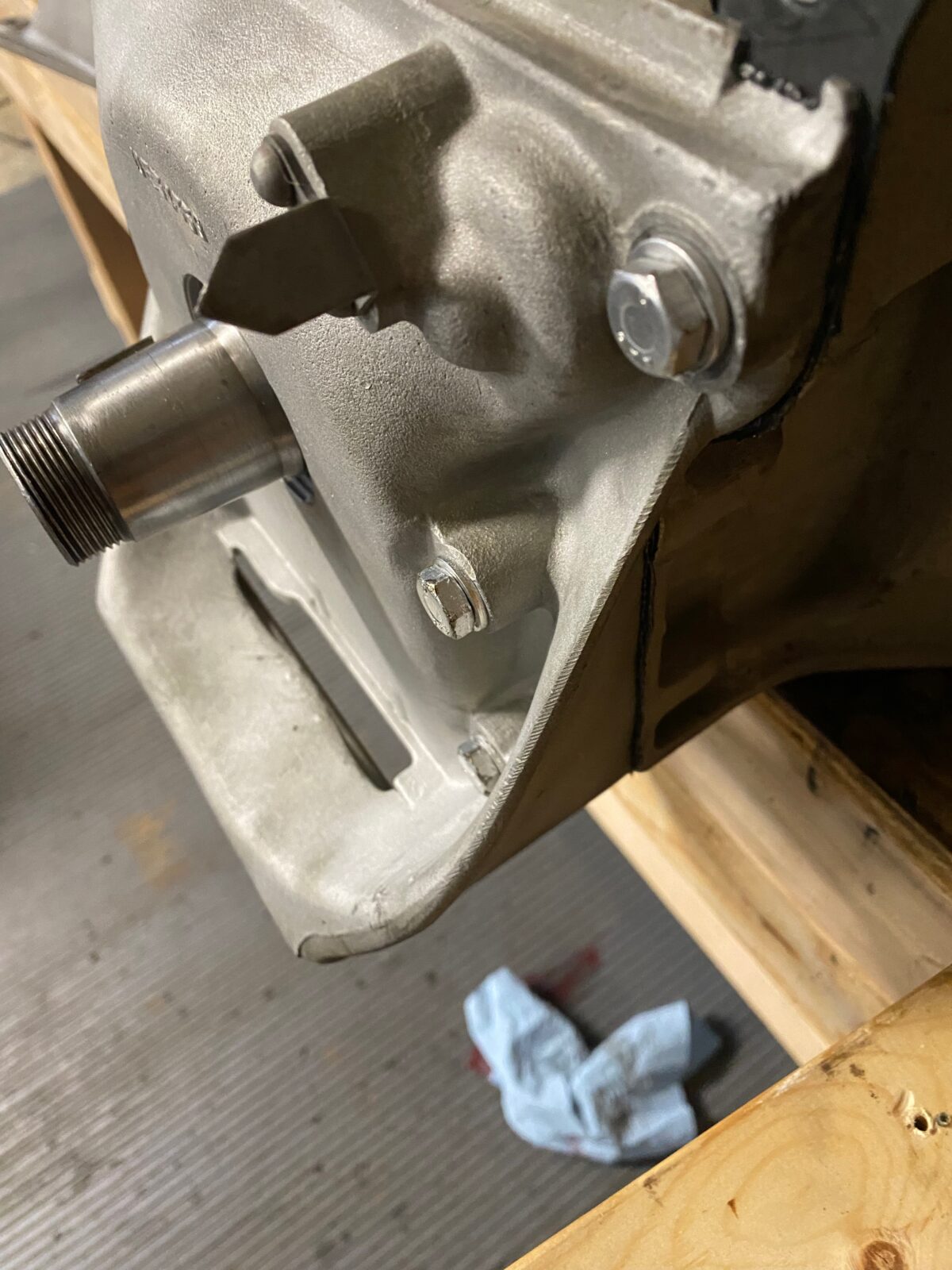
Engine reassembly begins!
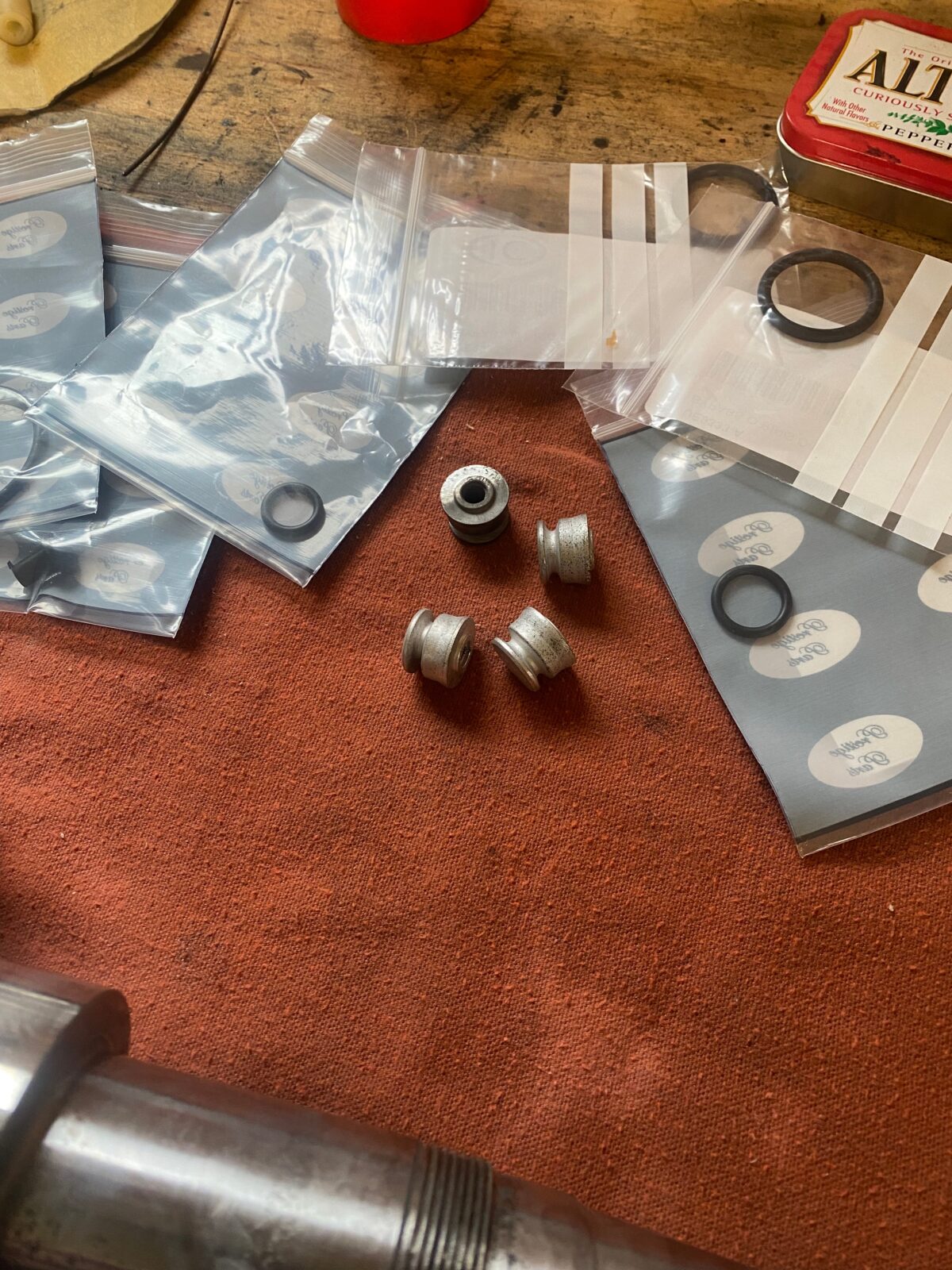
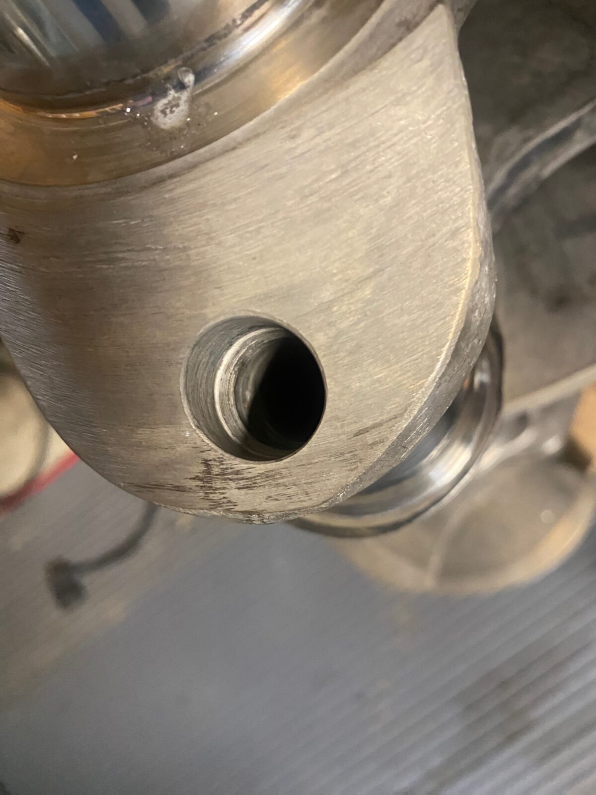
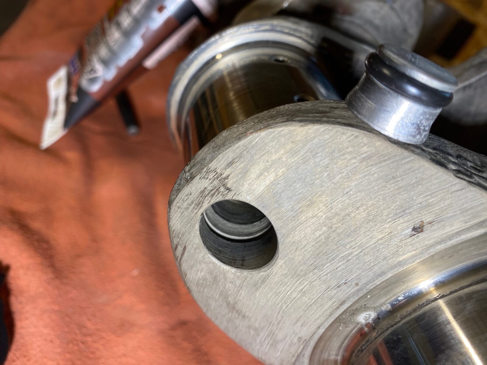
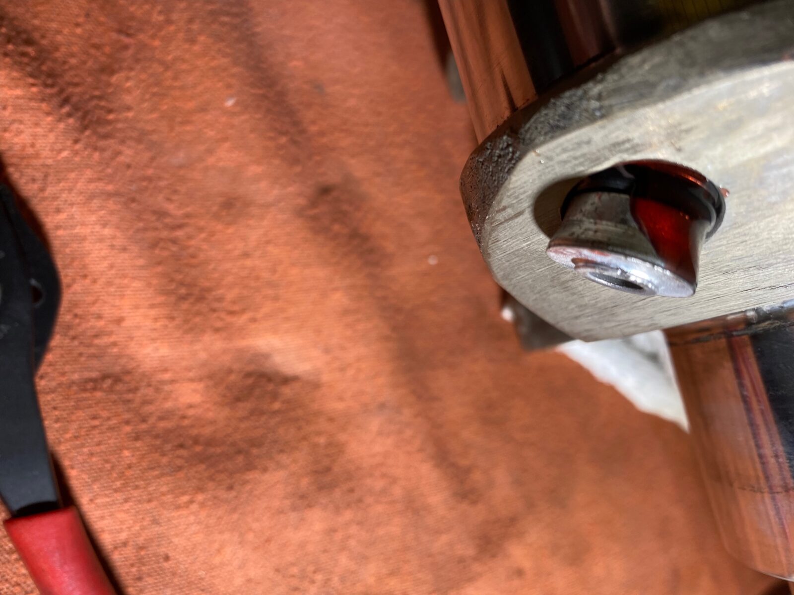
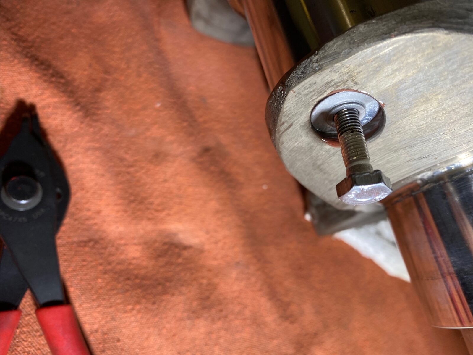
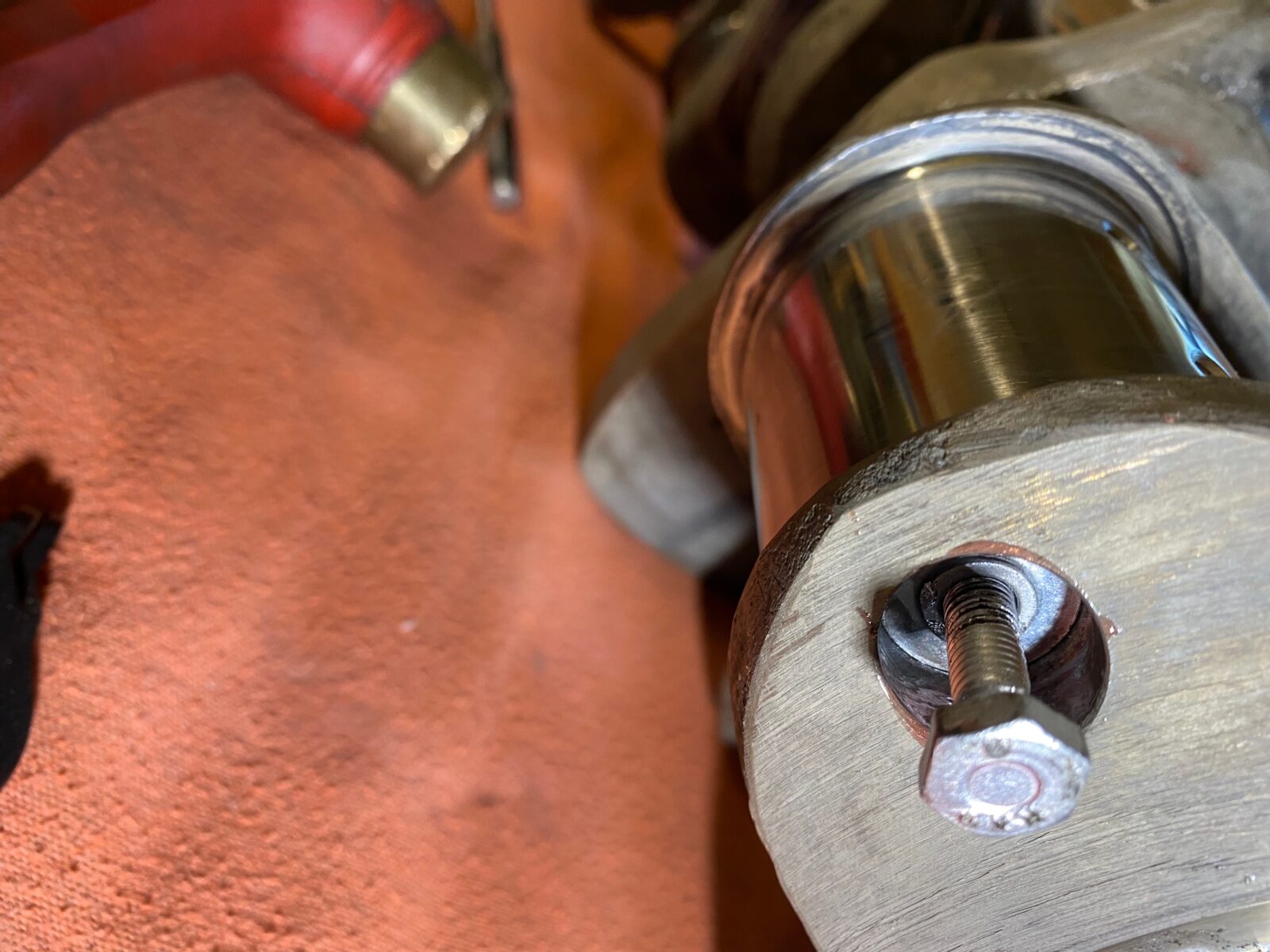
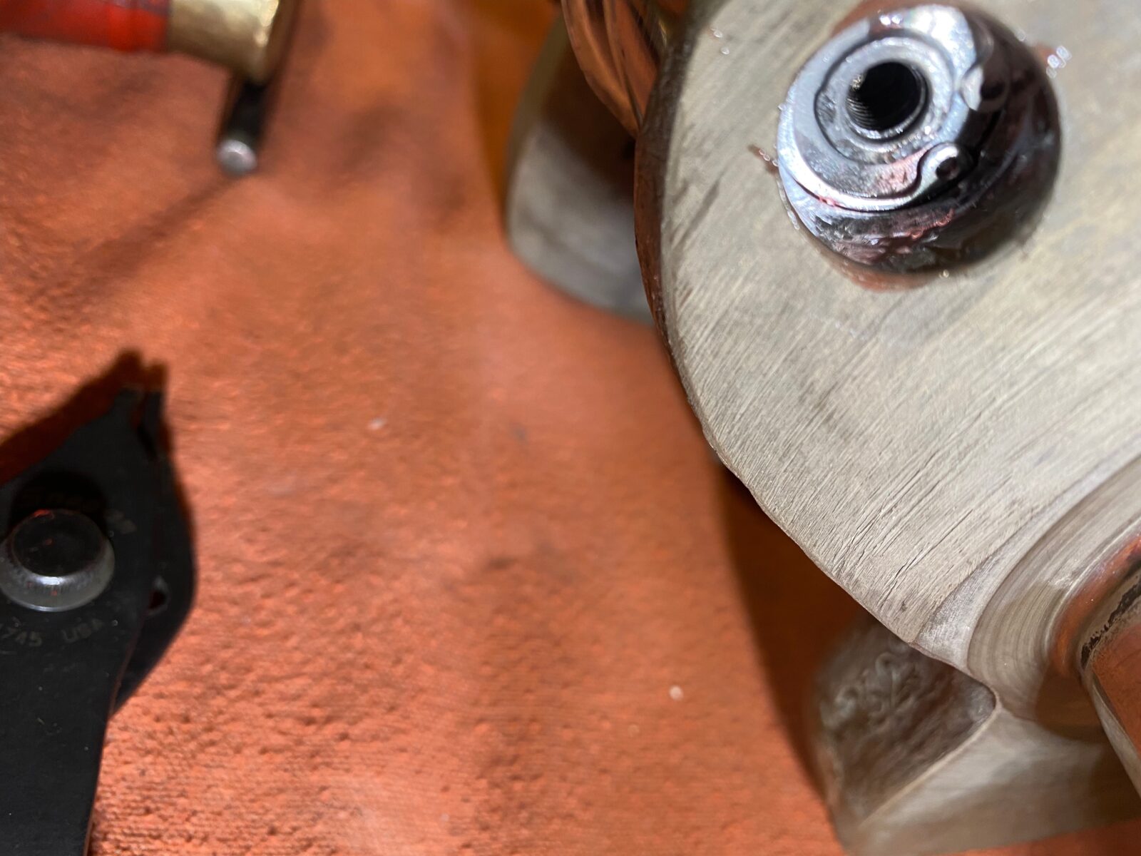
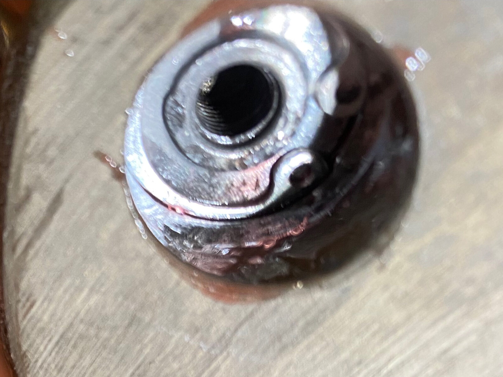
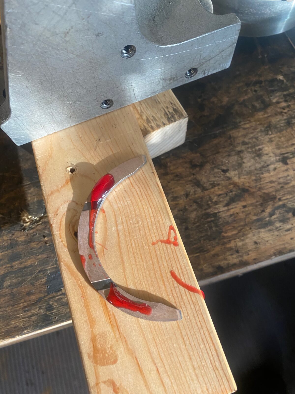
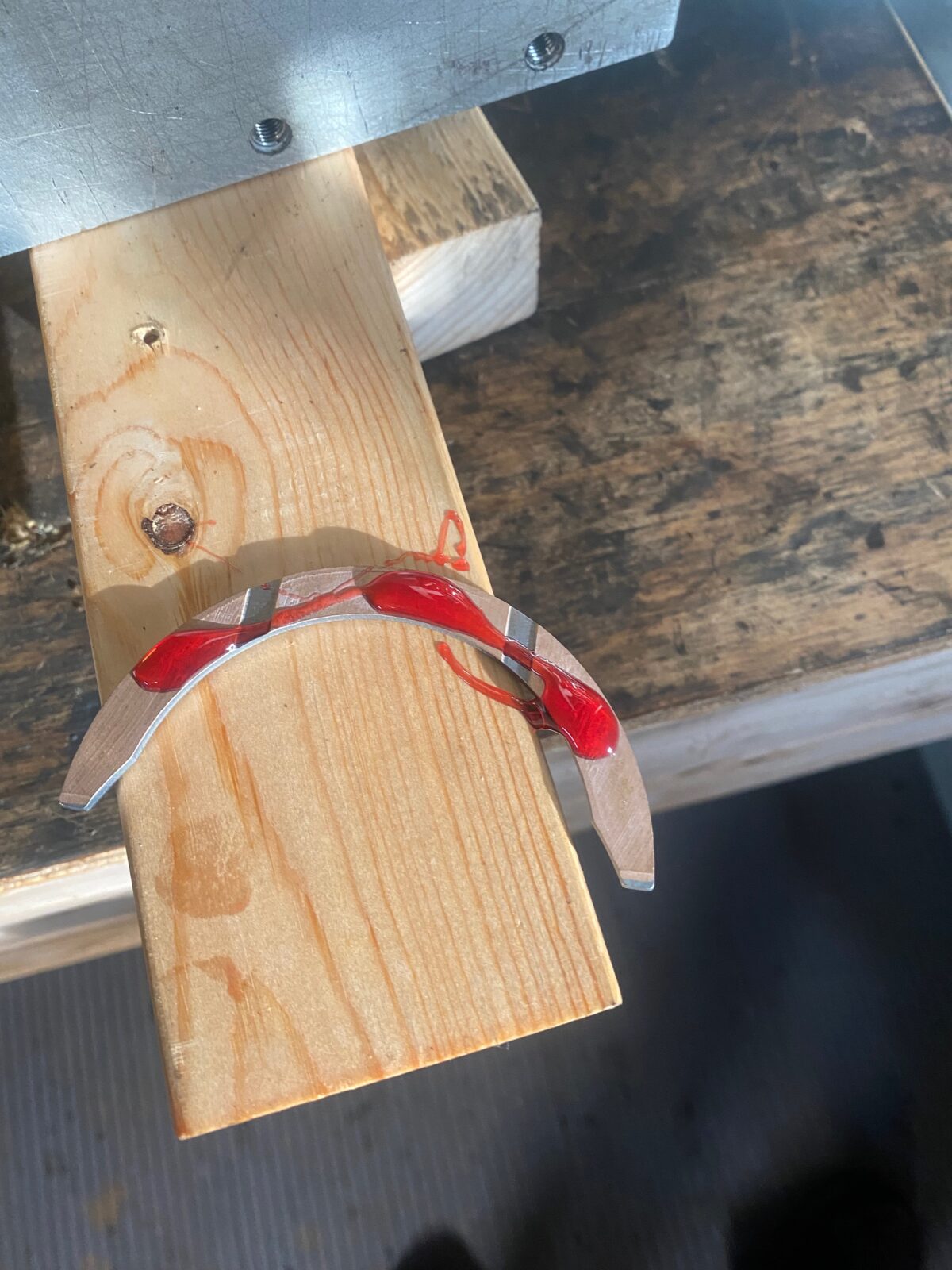
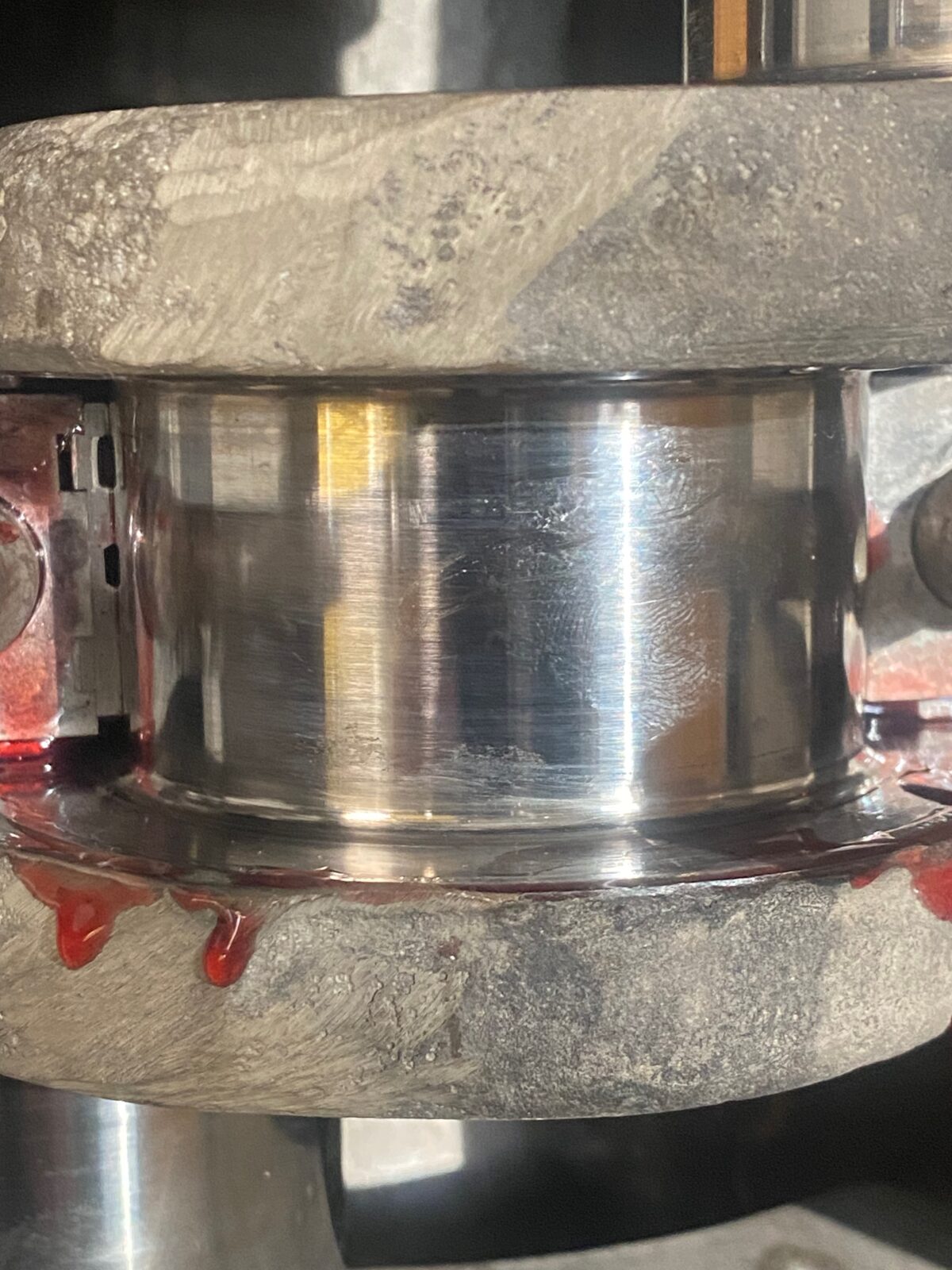
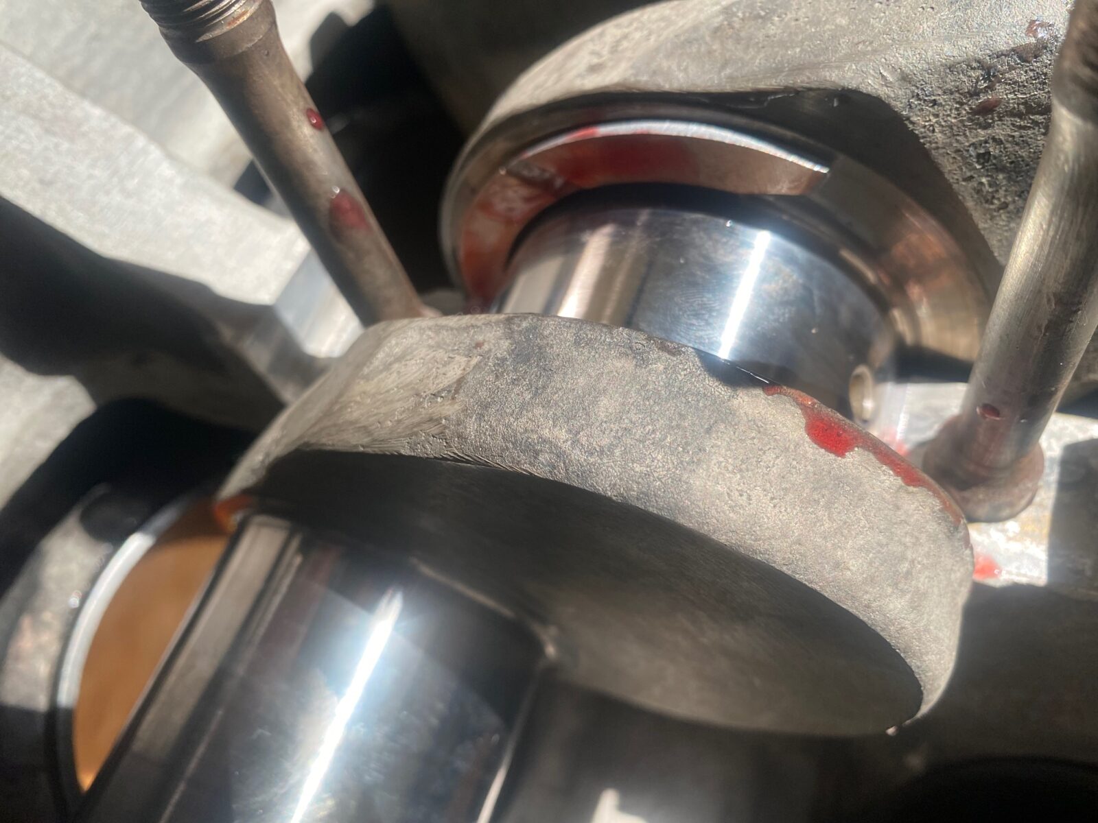
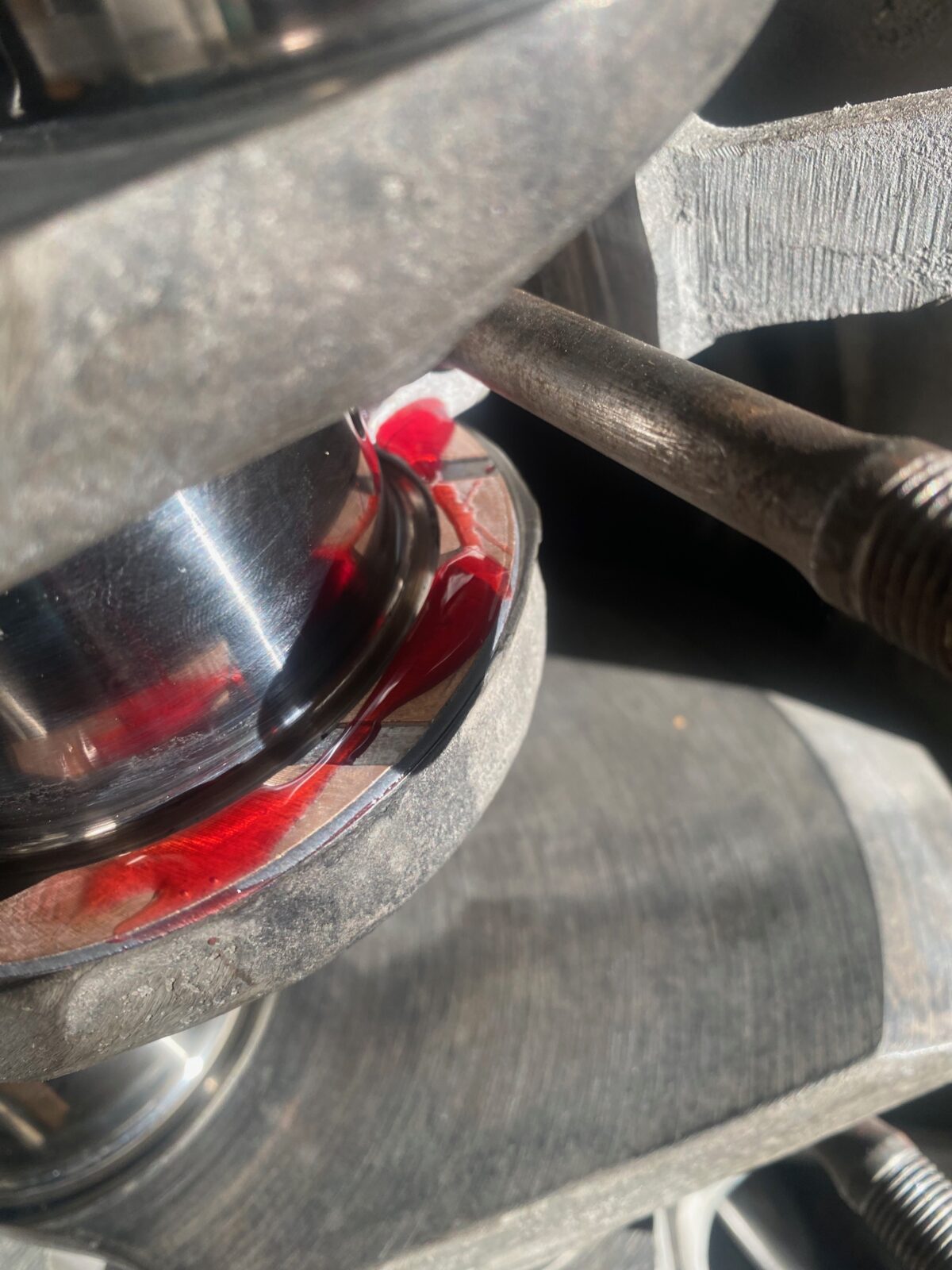
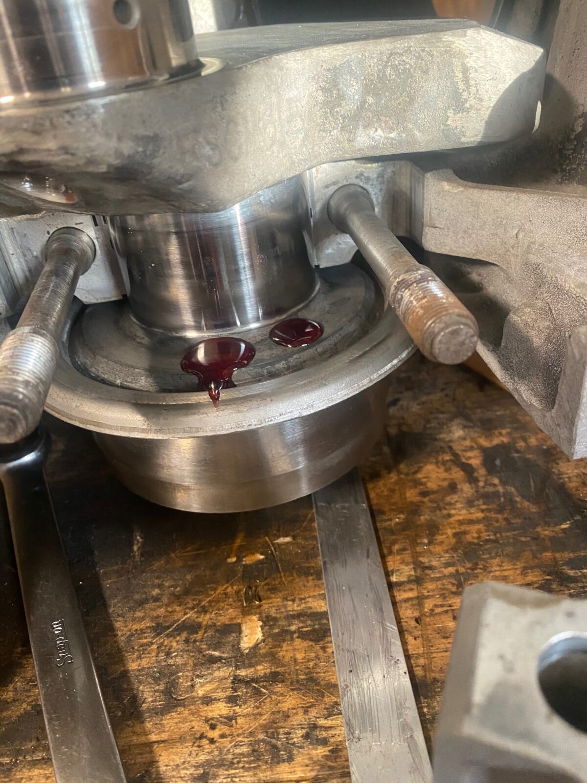
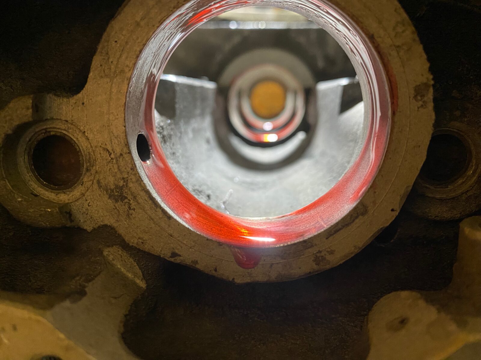
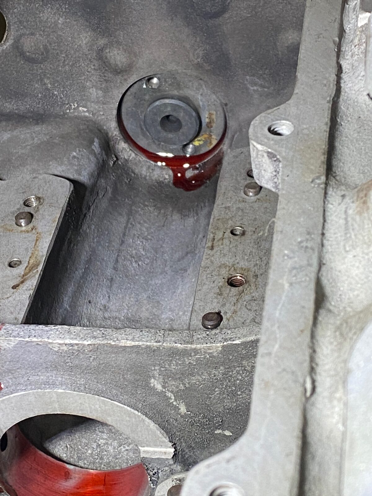
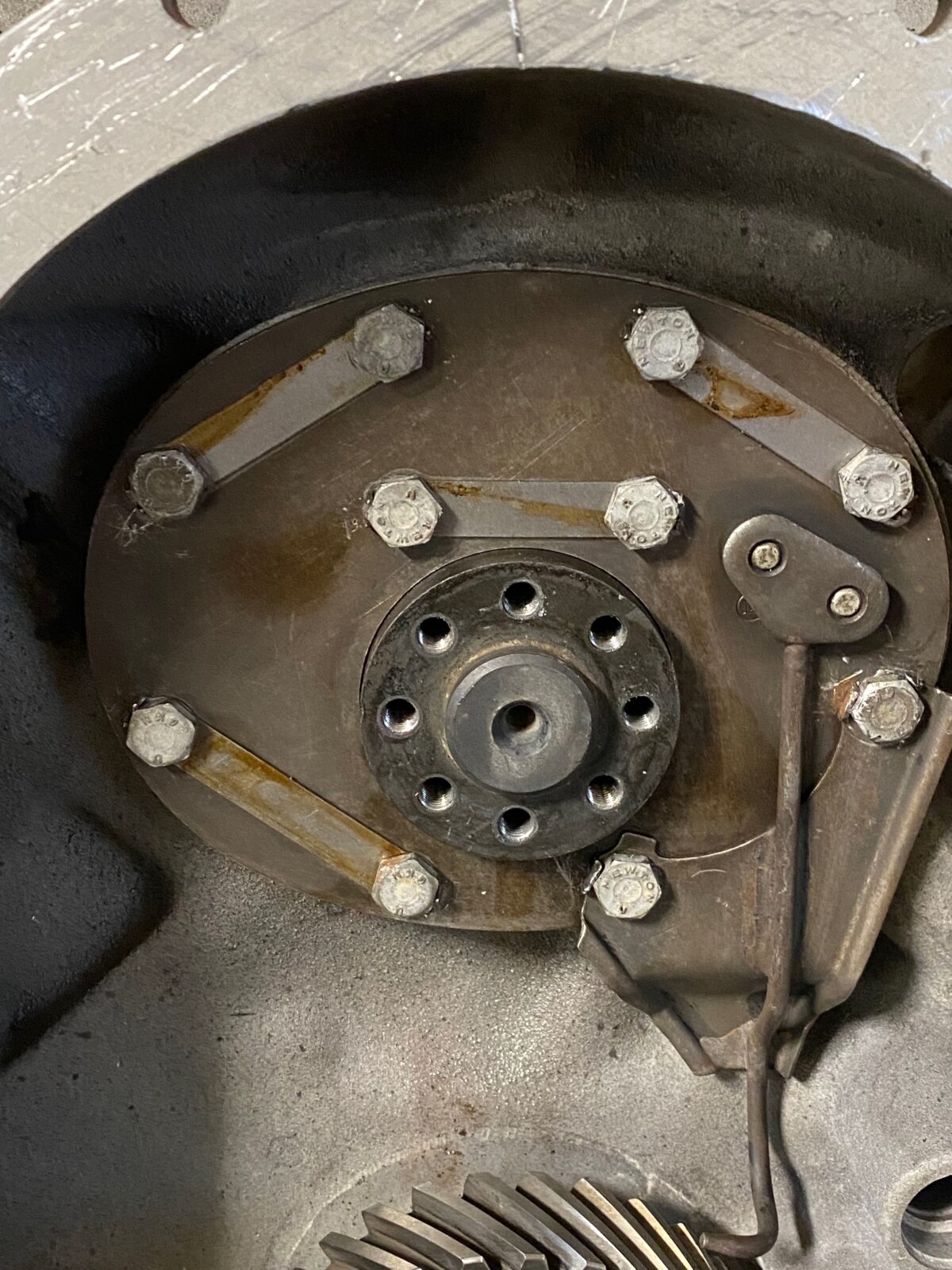
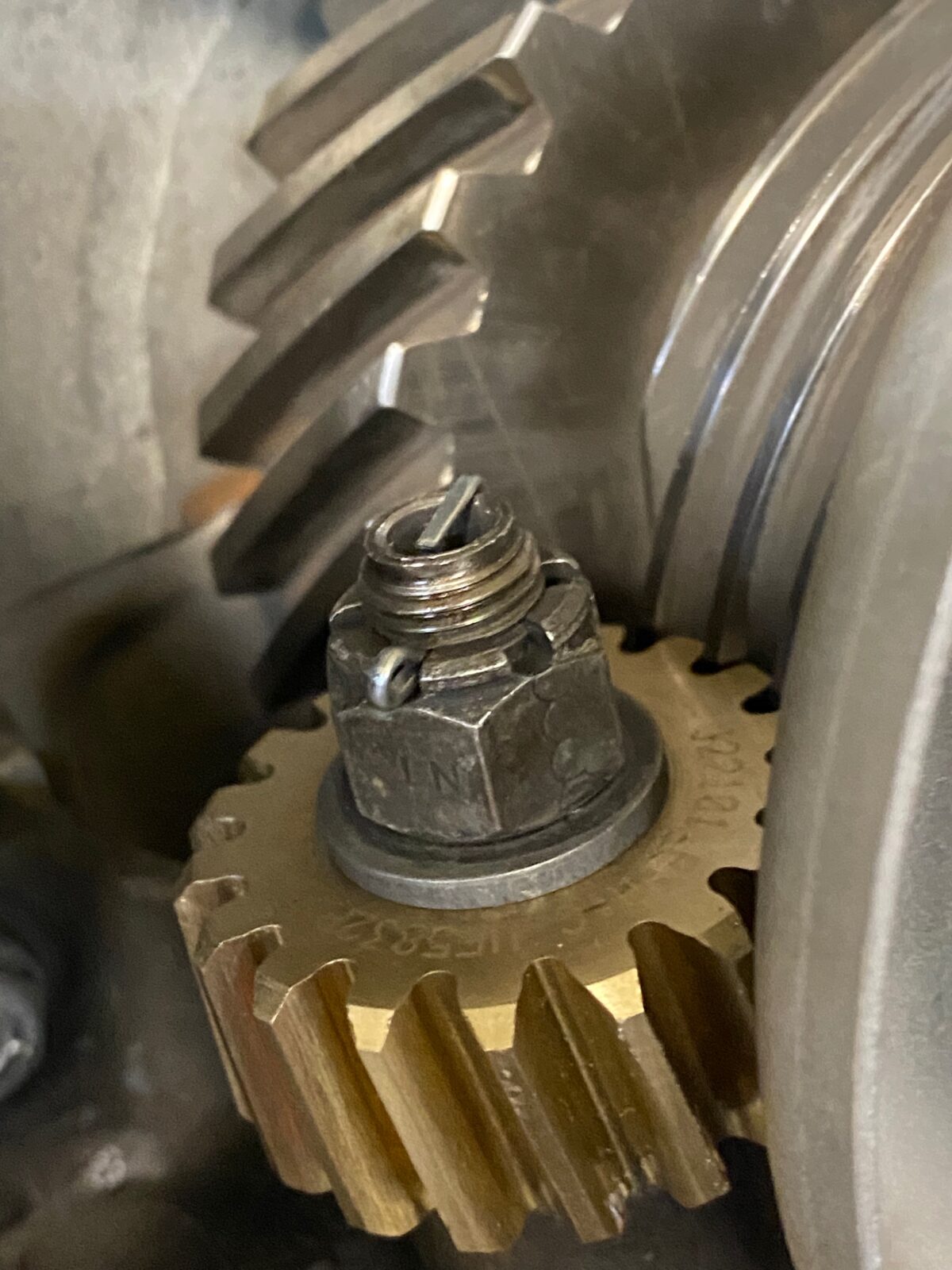
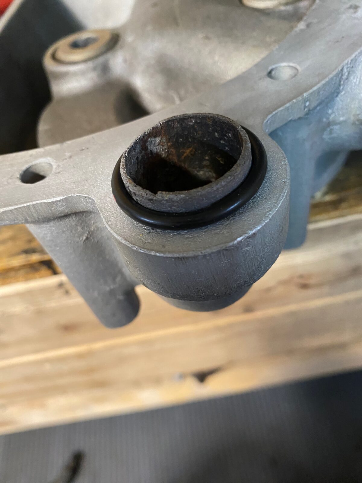
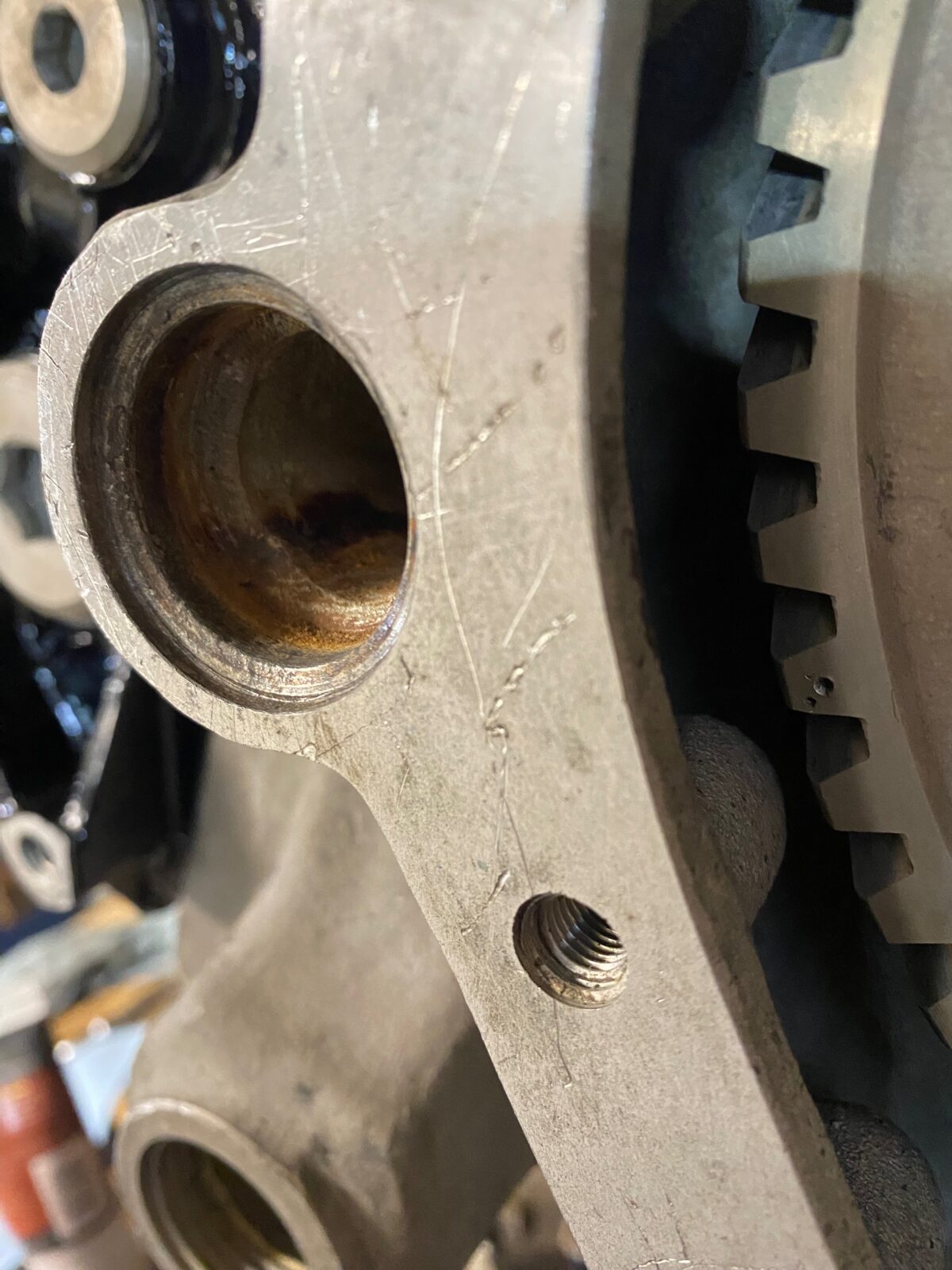
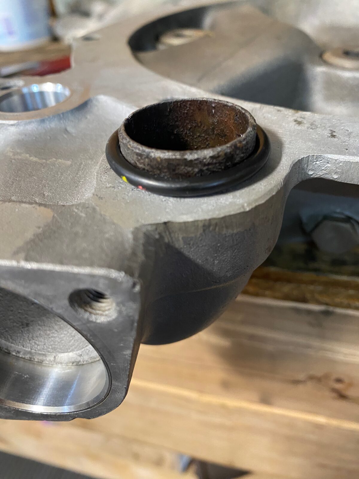
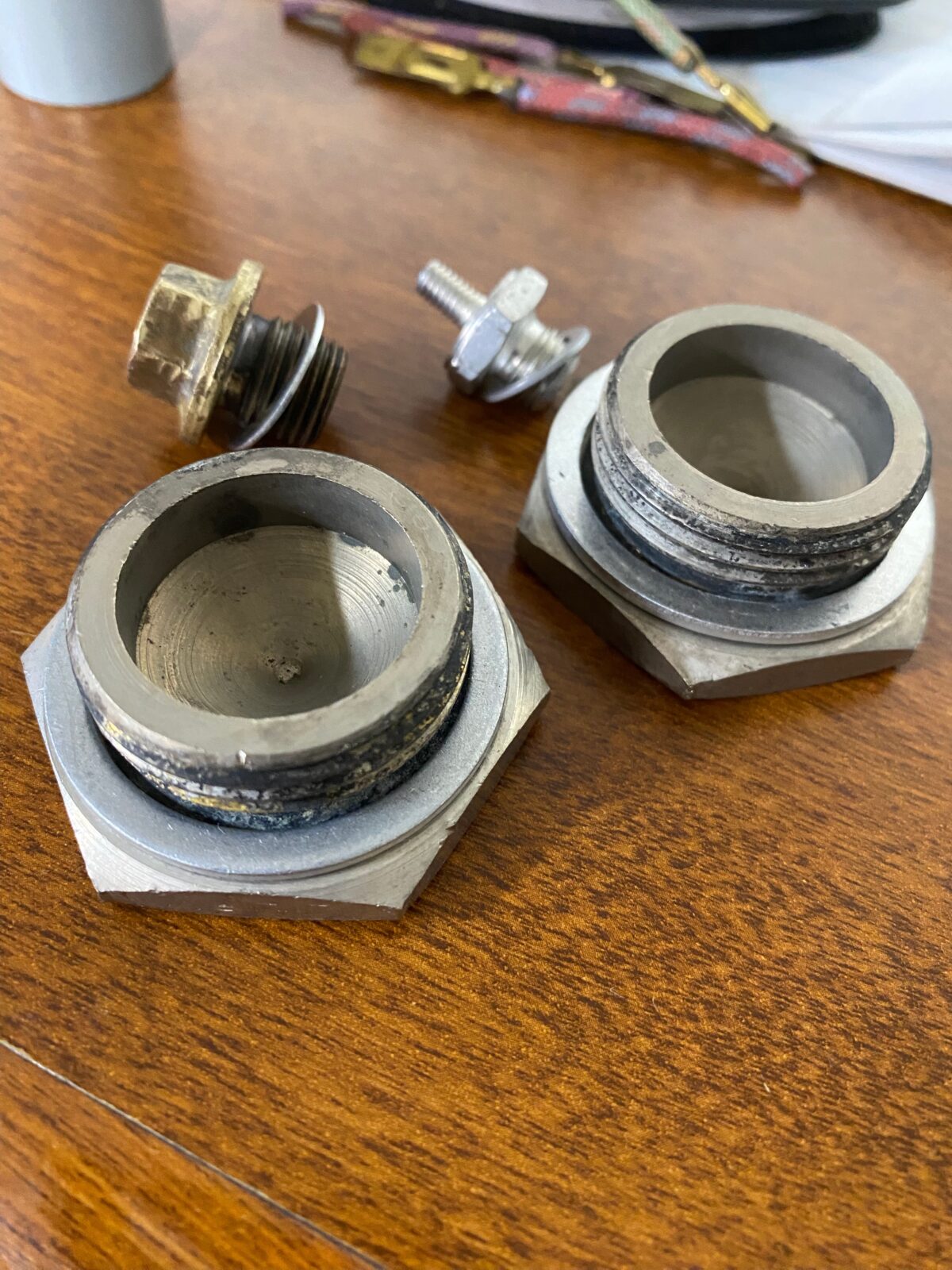
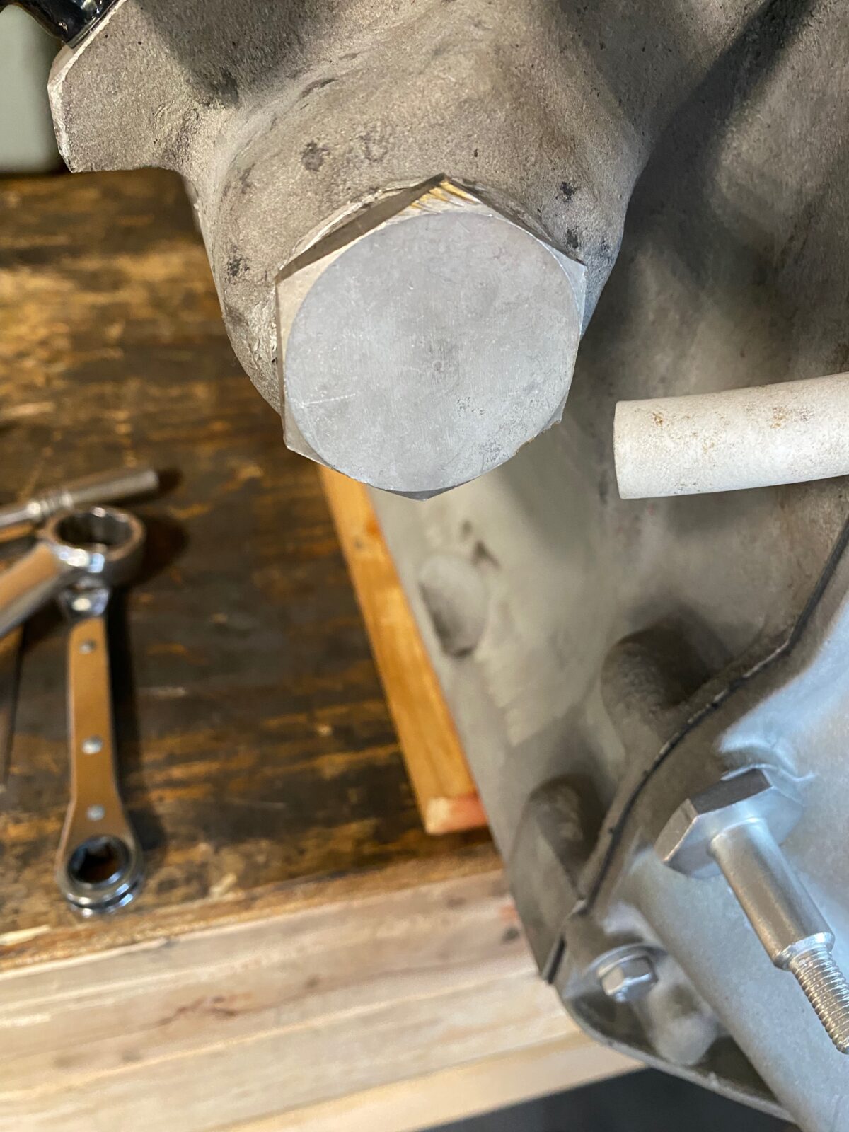
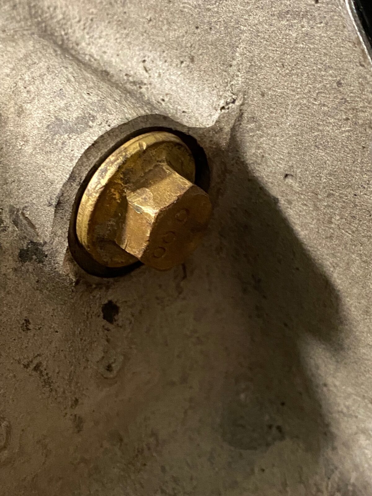
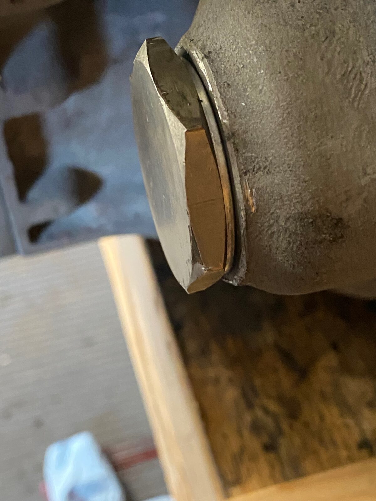
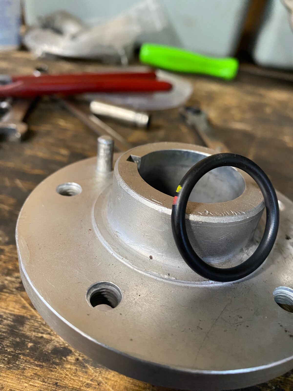
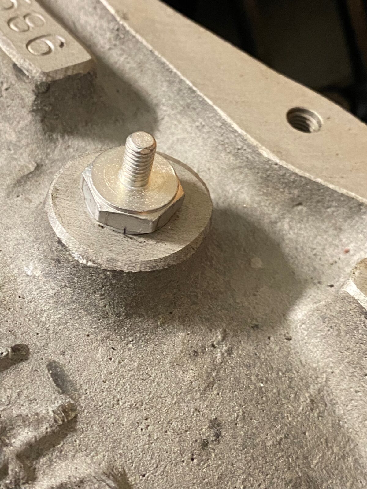
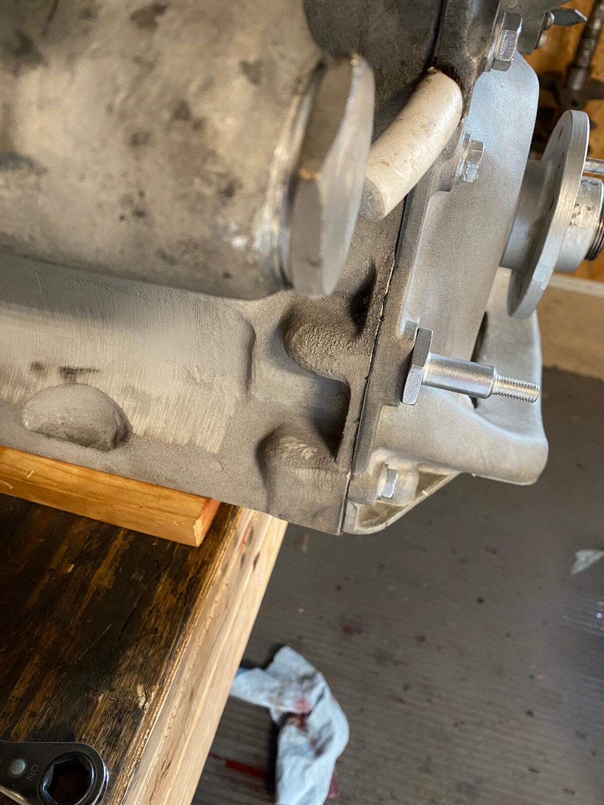
Below we are replacing the “O” rings on the sludge trap plugs of the crankshaft. (Click on photos for full view)
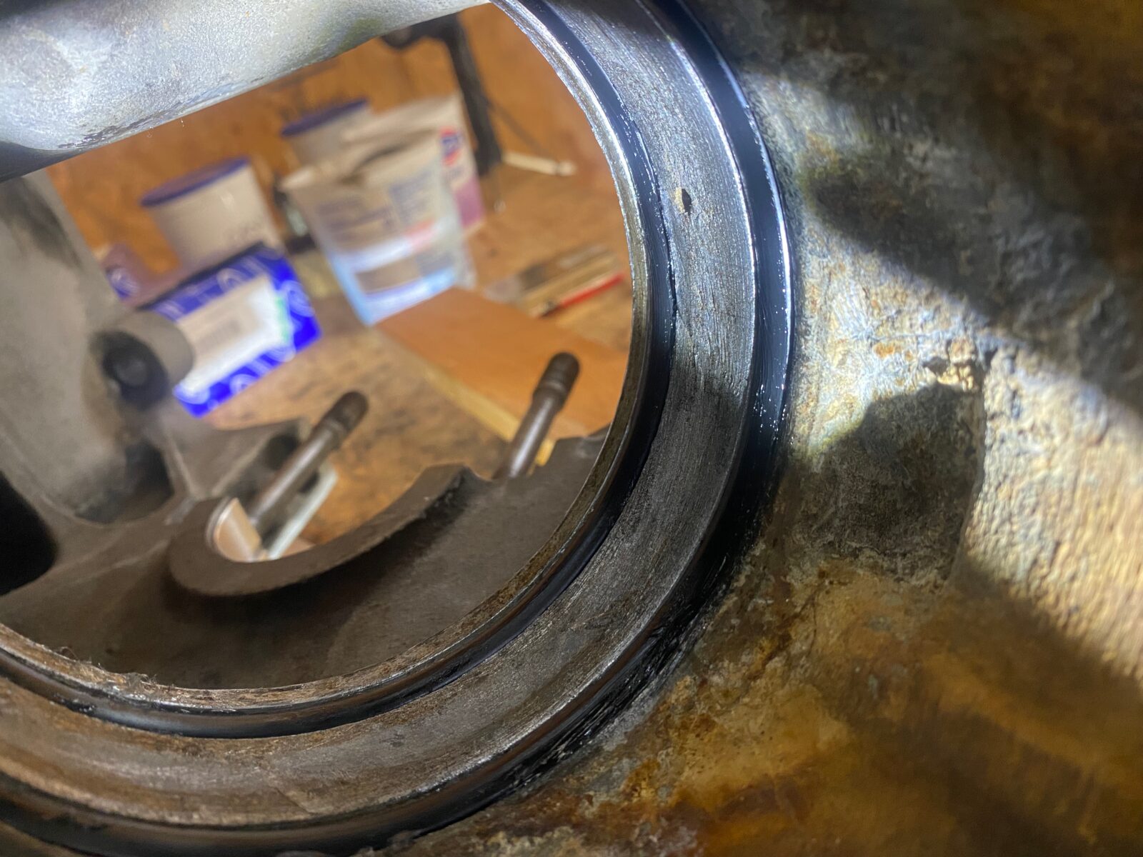
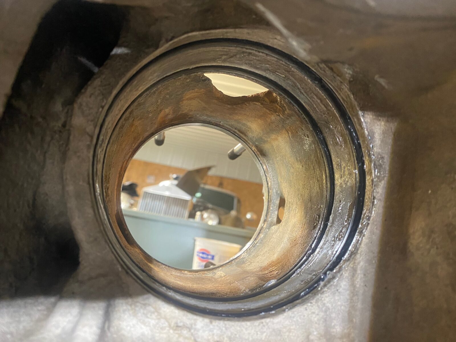
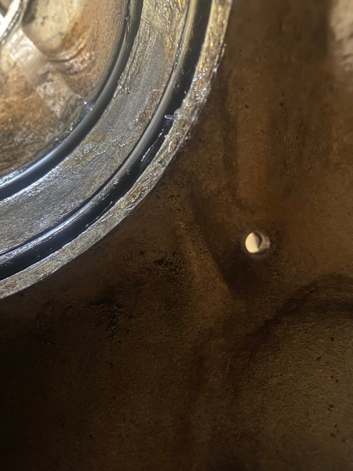
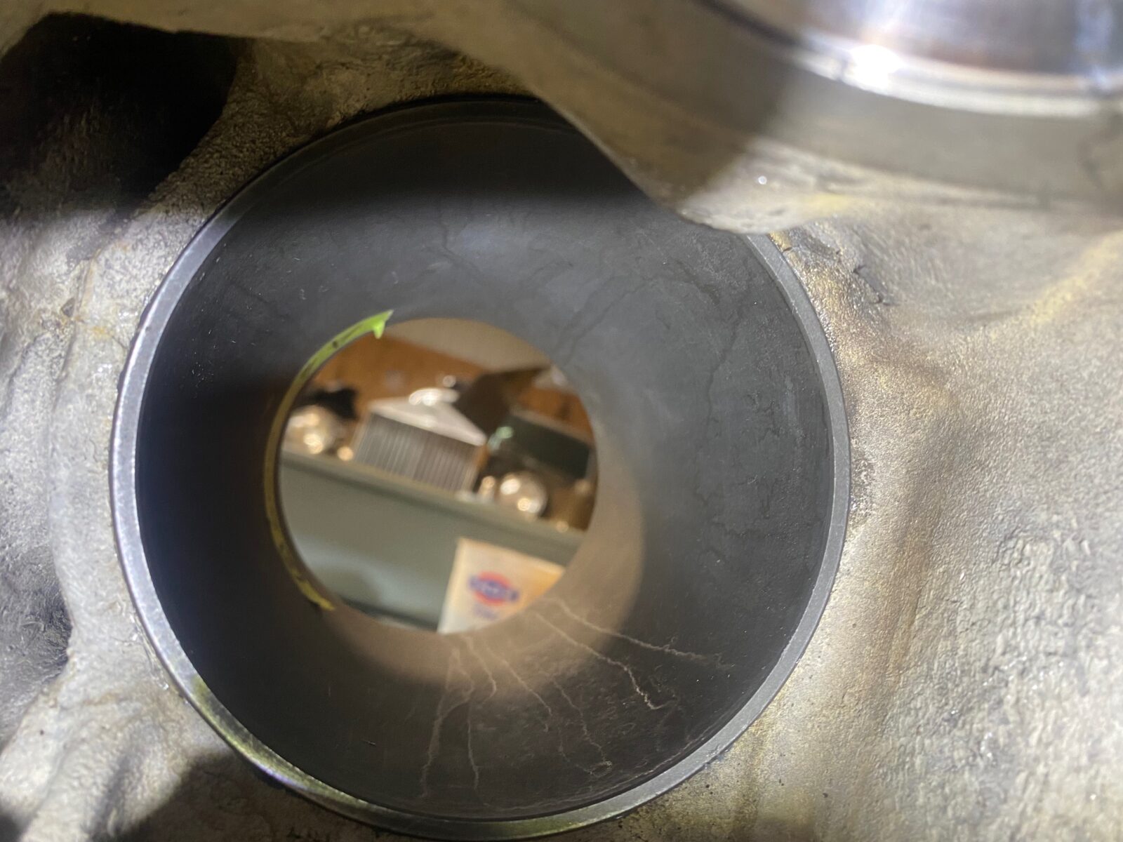
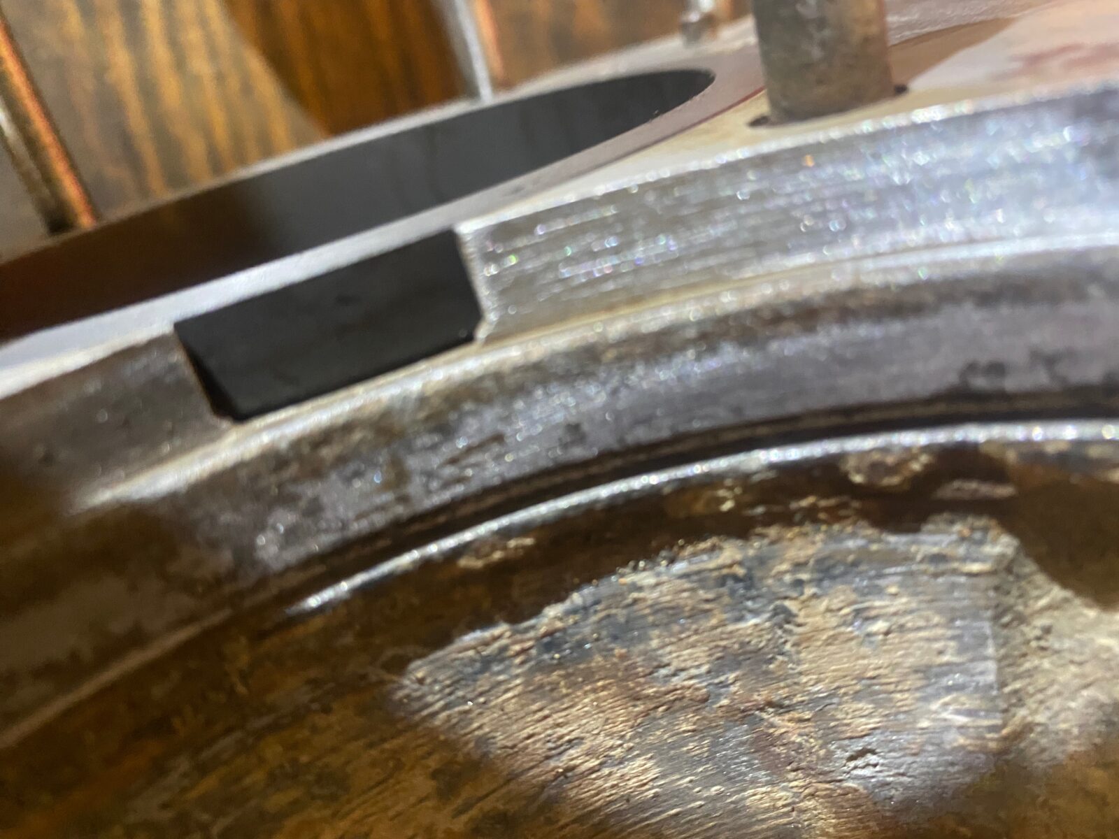
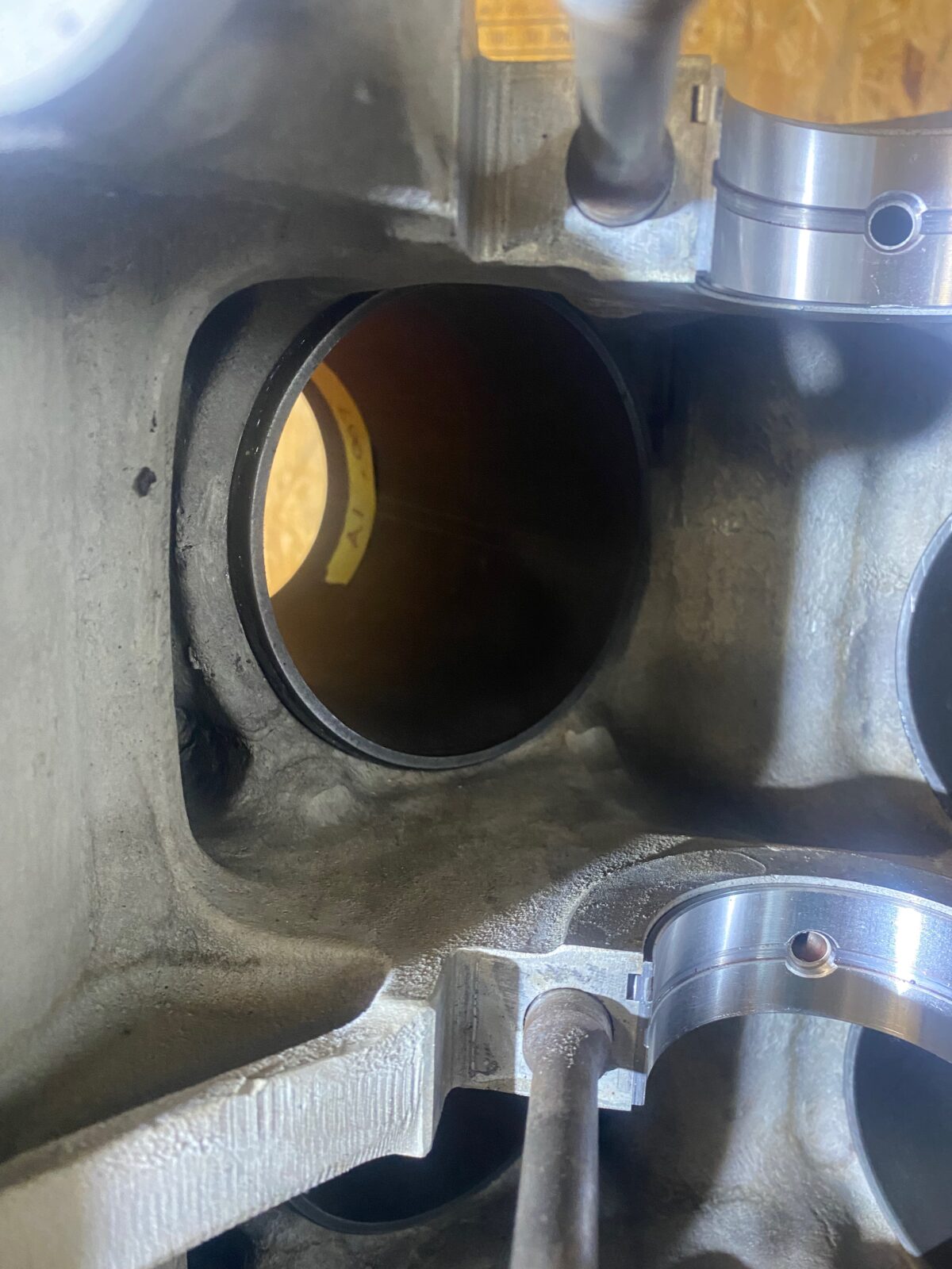
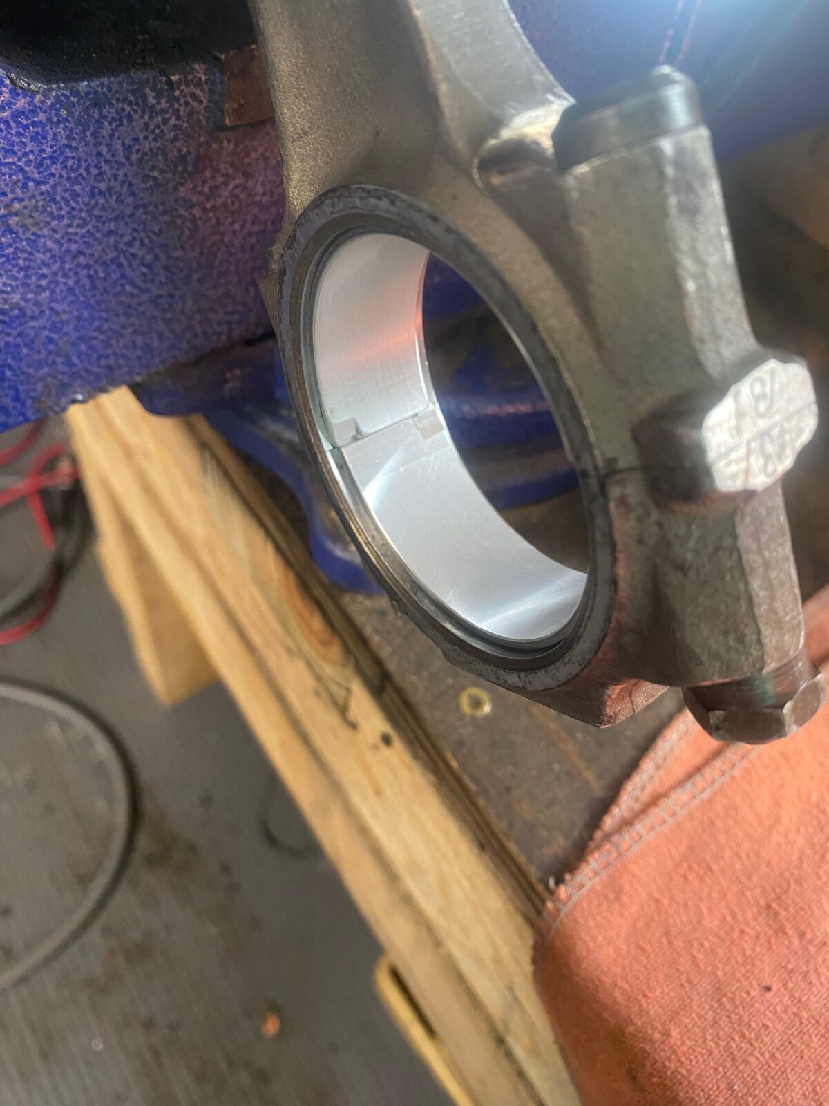
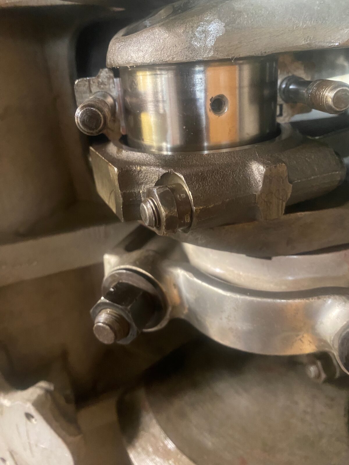
Fitting the liners to the crankcase
Fitment of new liner seals to the crankcase. (Click on photos for full view)
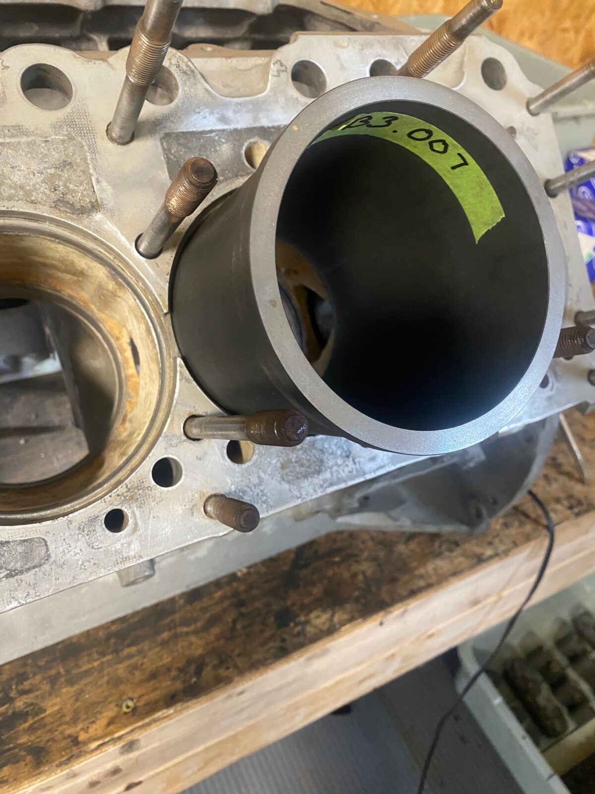
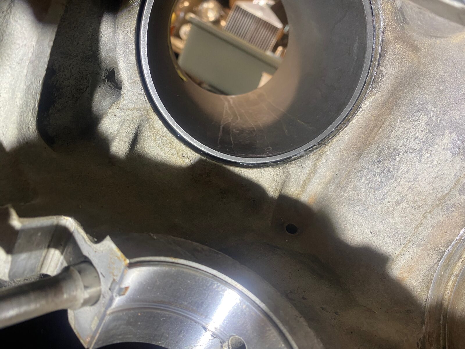
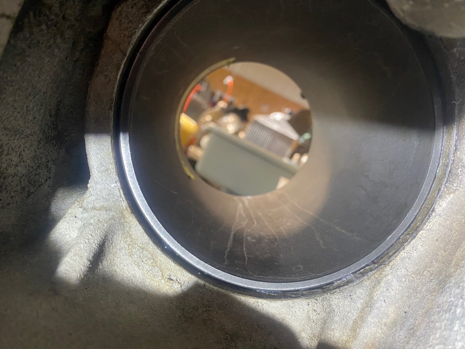
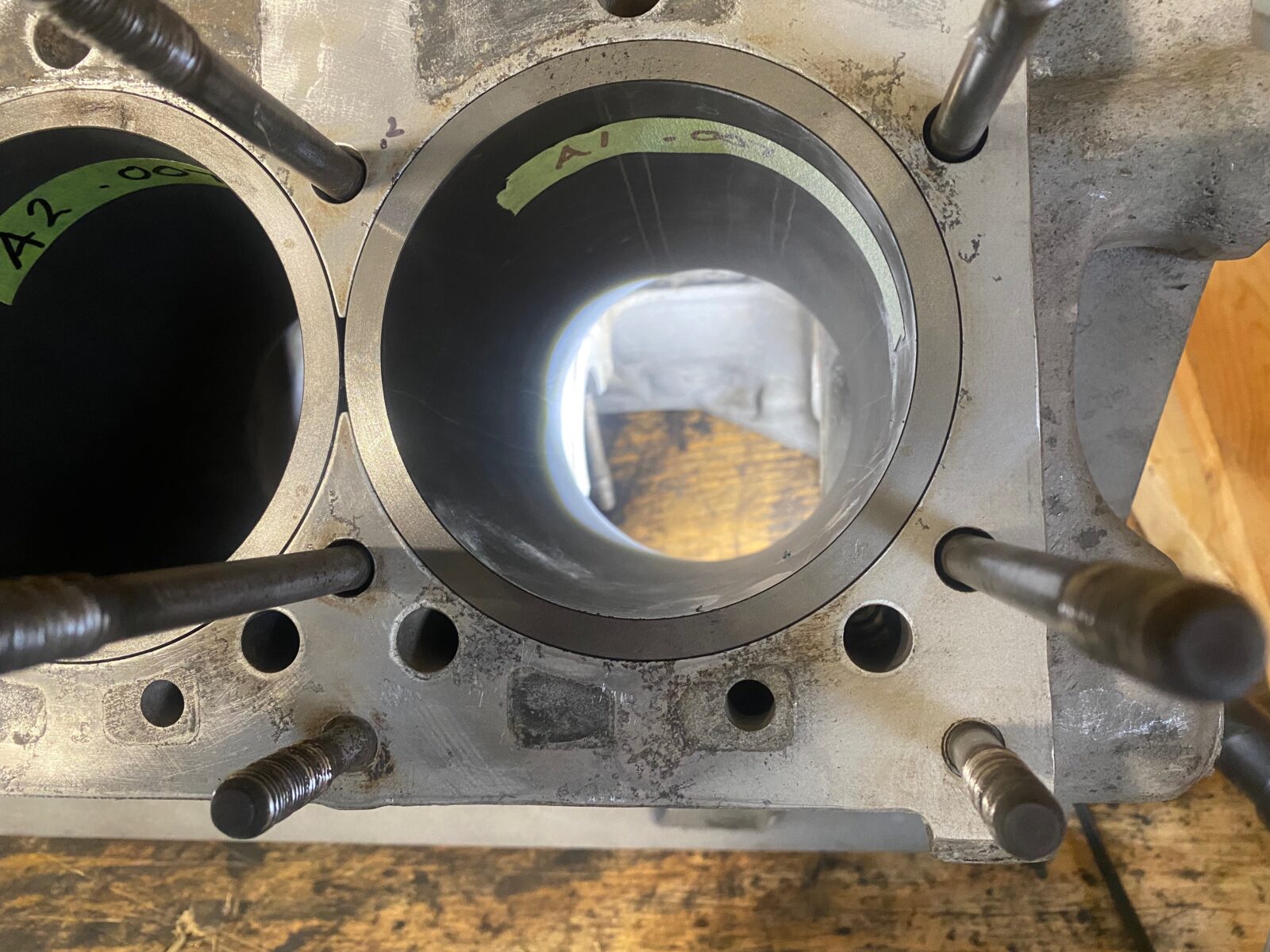
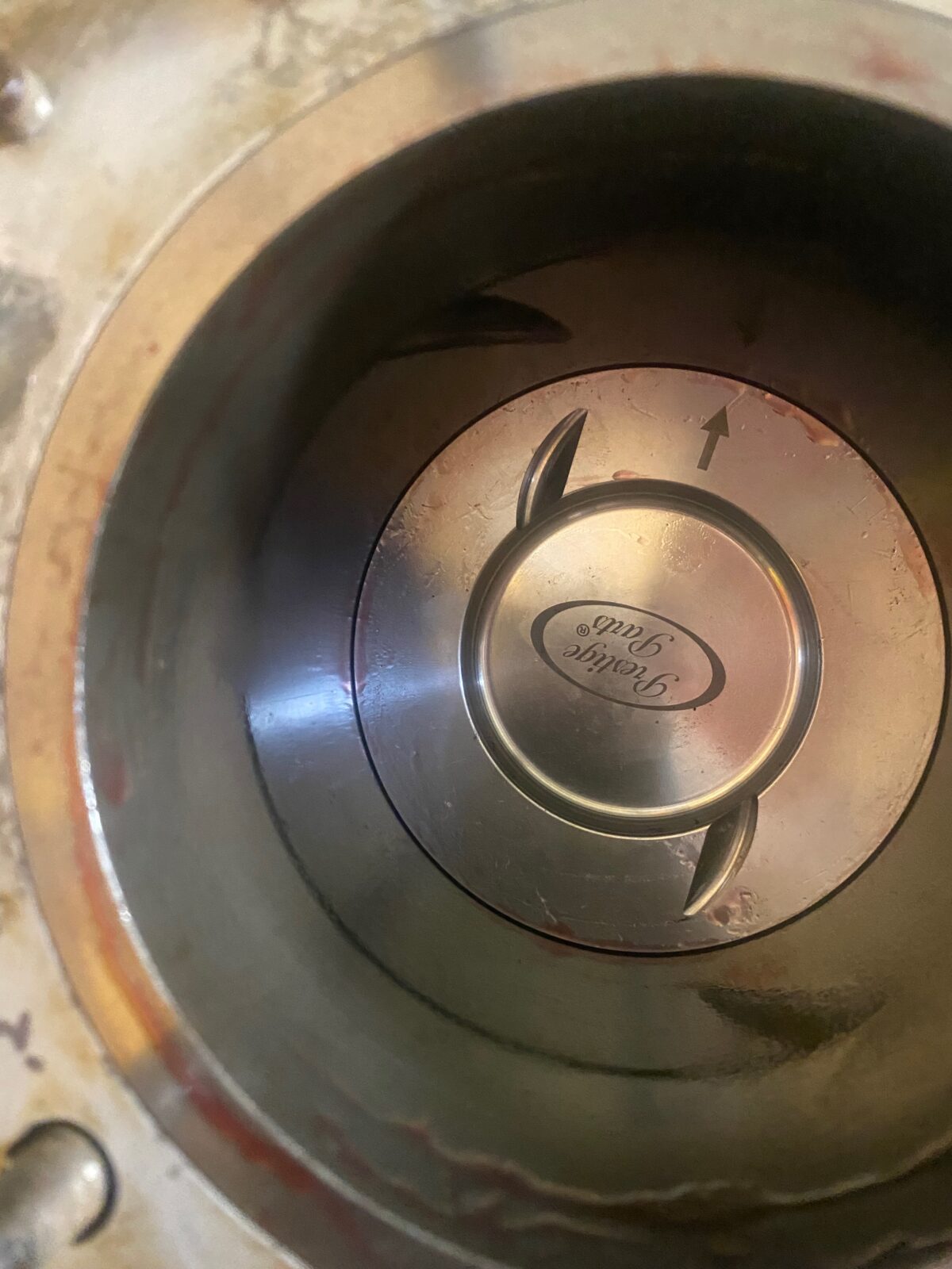
Next we insert the liners into the newly installed seals and into the crankcase.
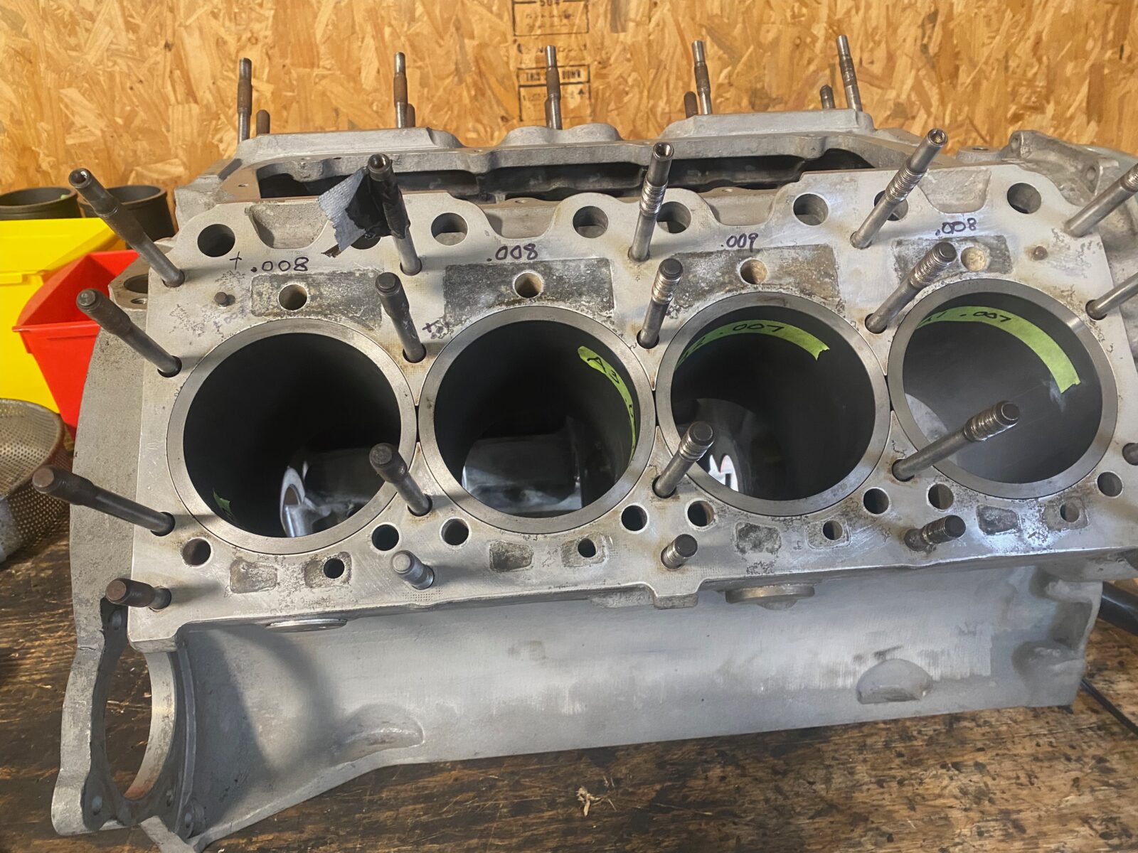
The photos below show the liners correctly installed.
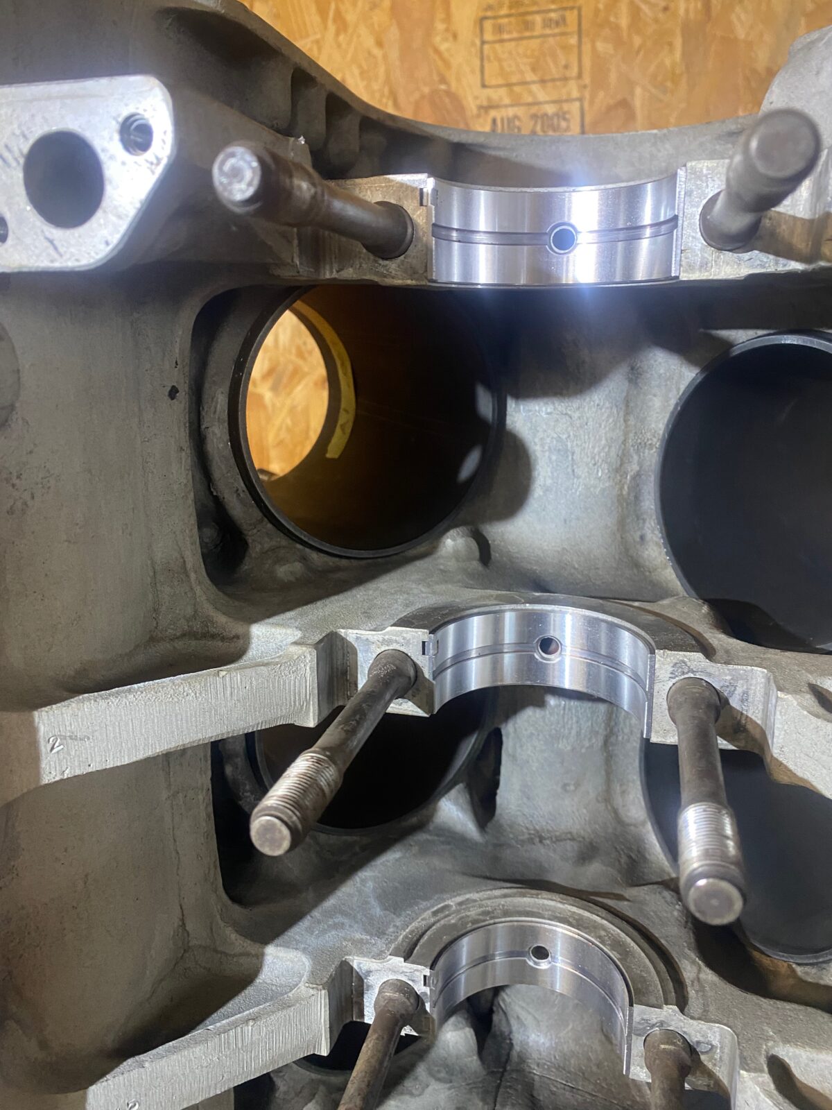
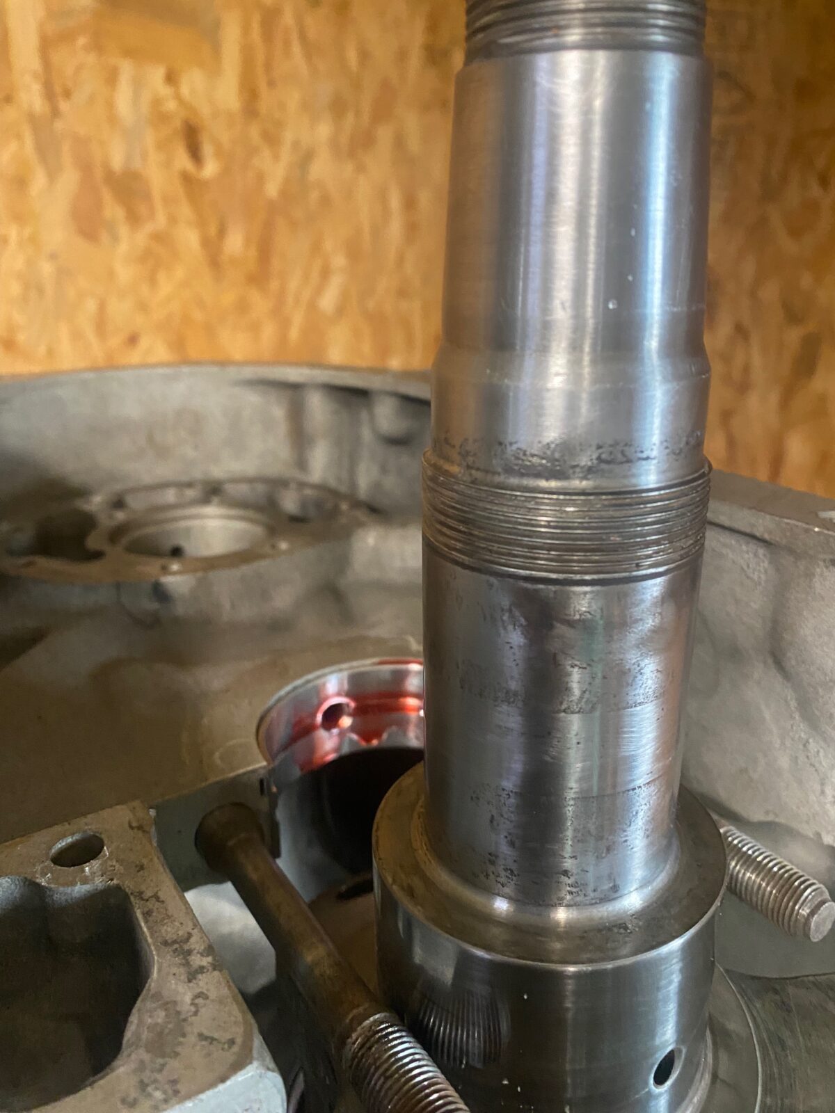
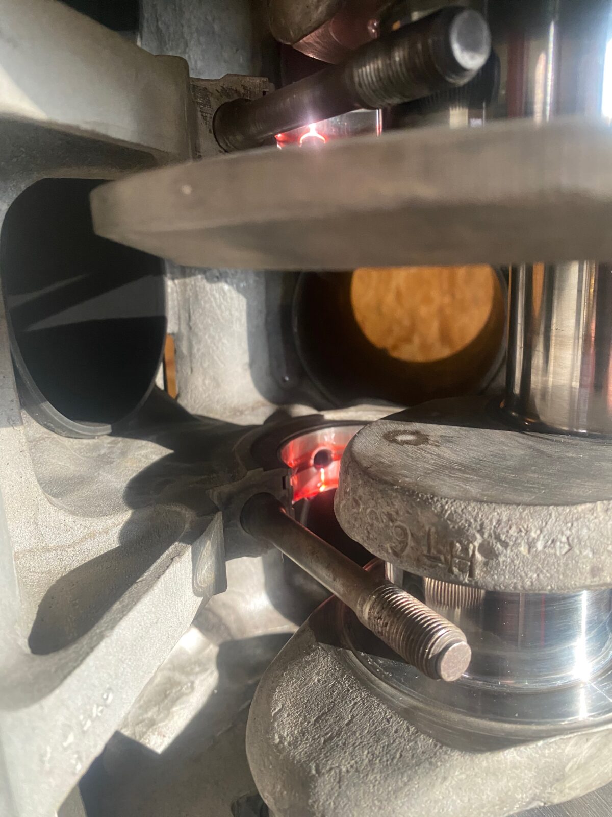
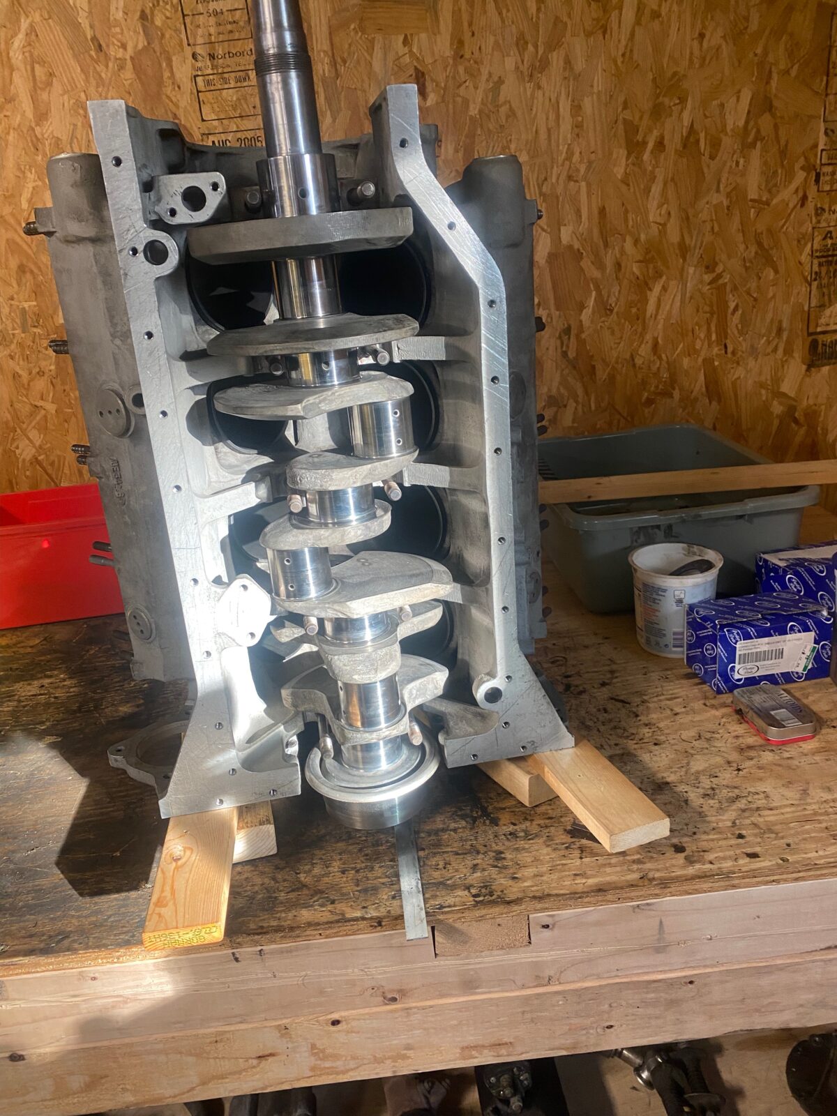
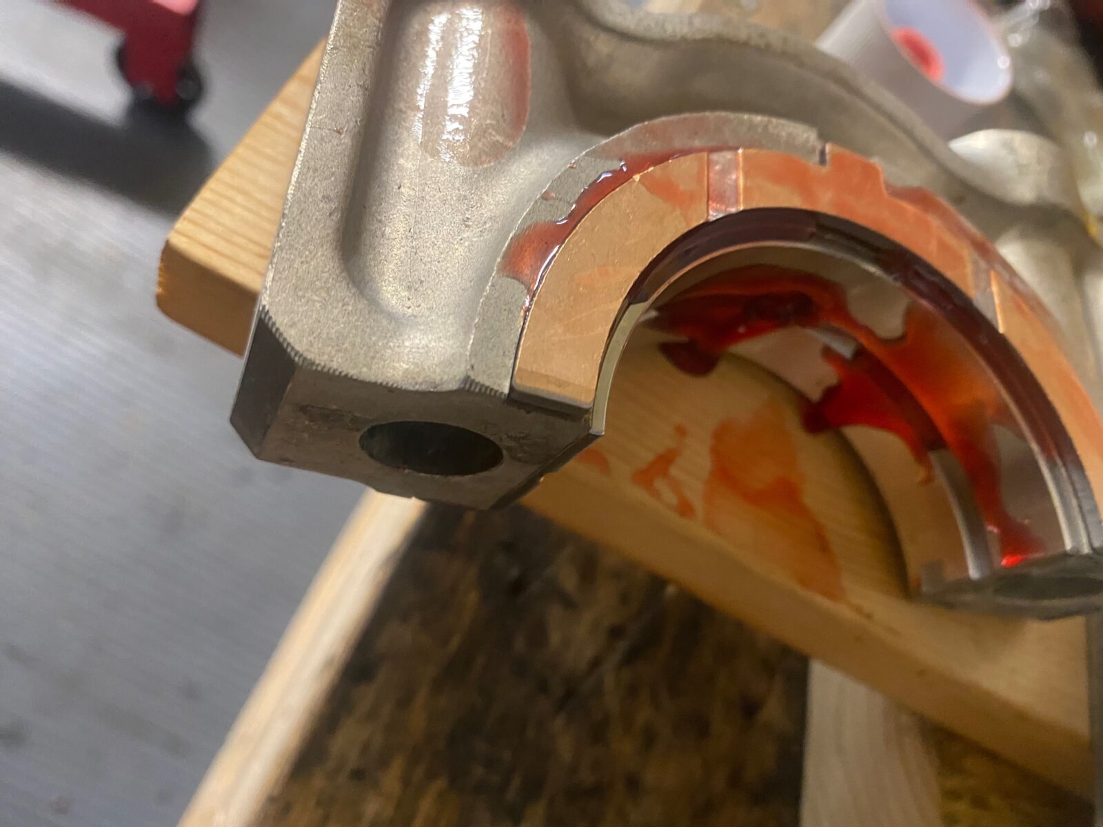
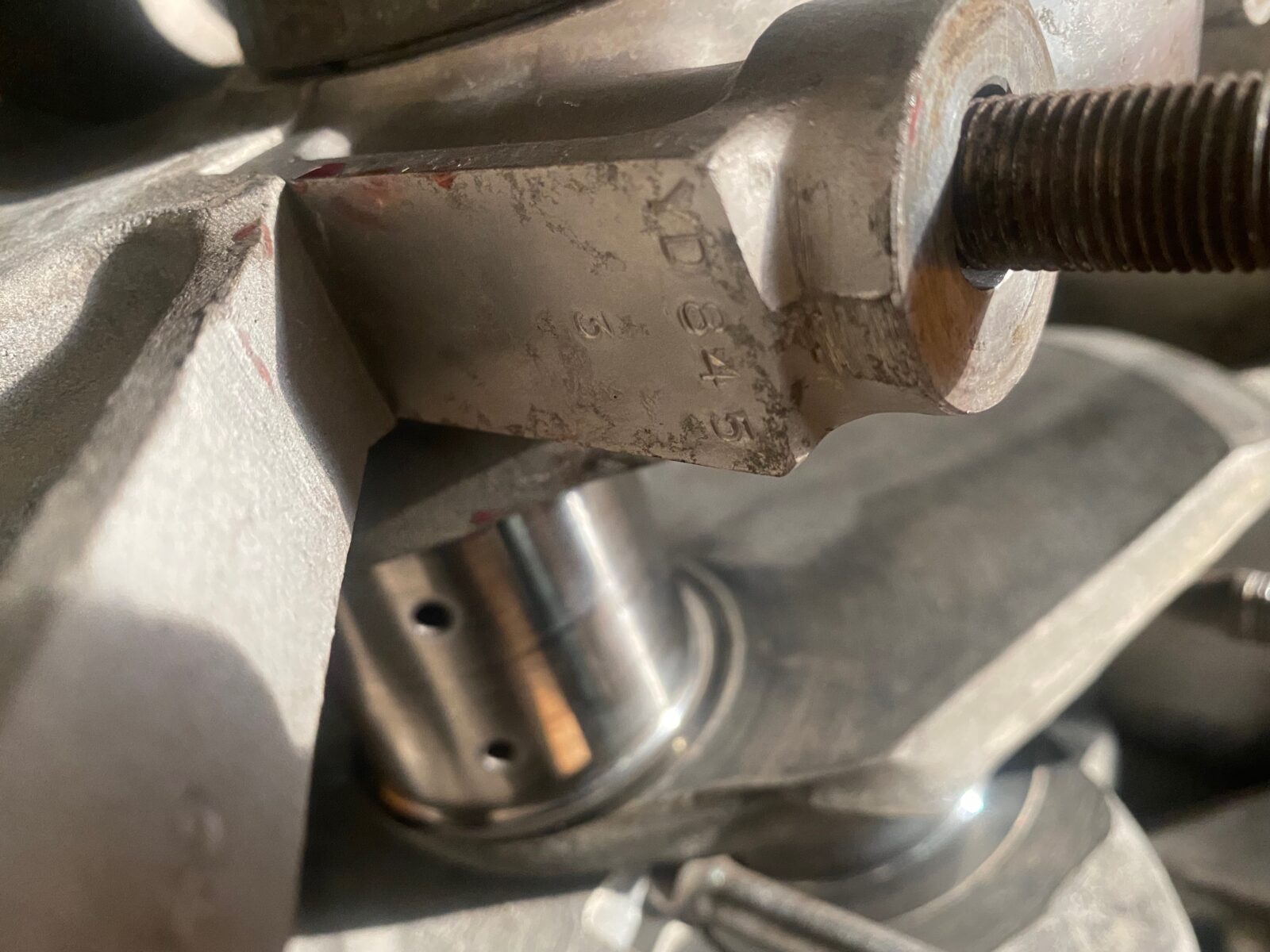
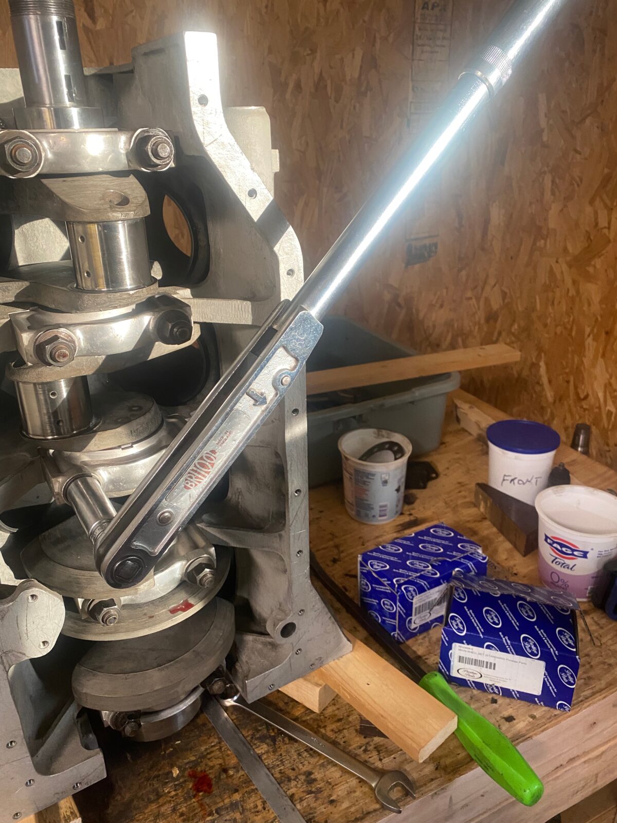
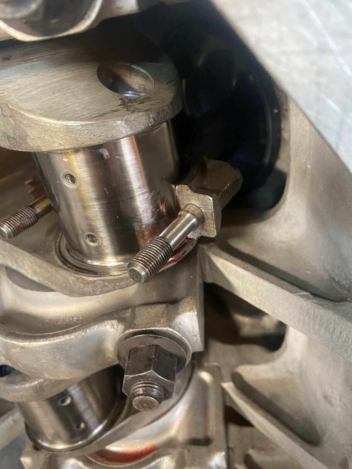
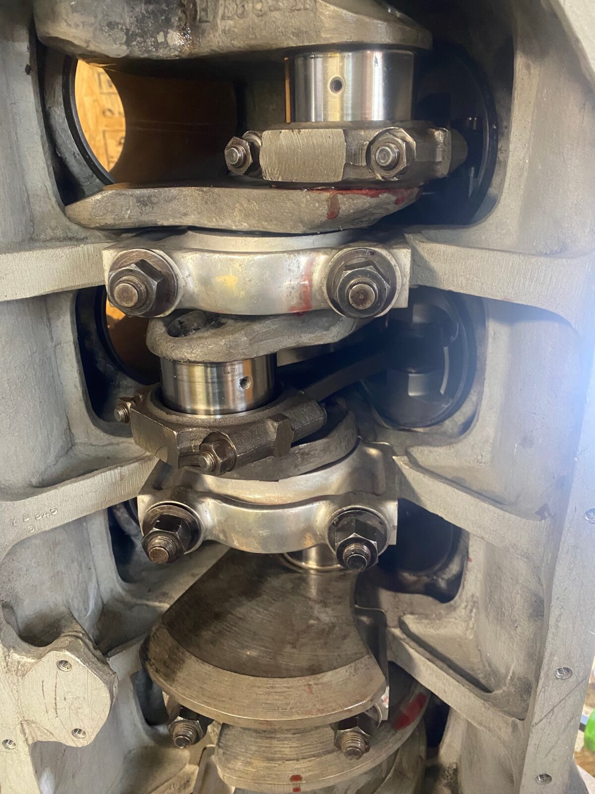
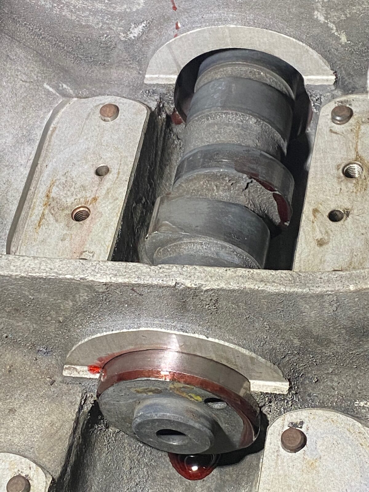
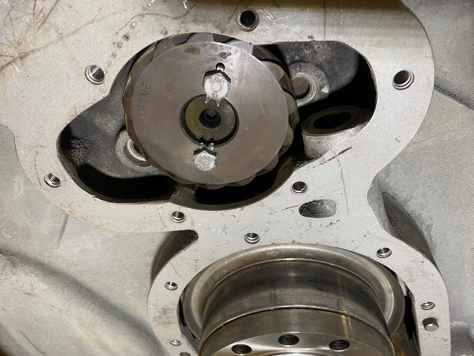
Crankshaft installation
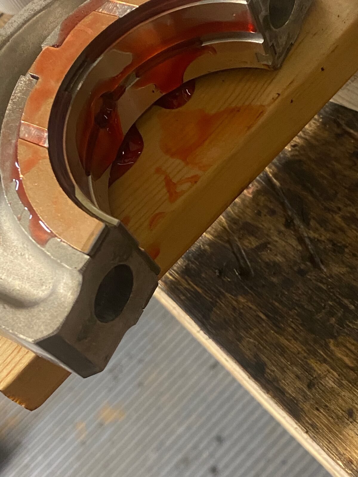
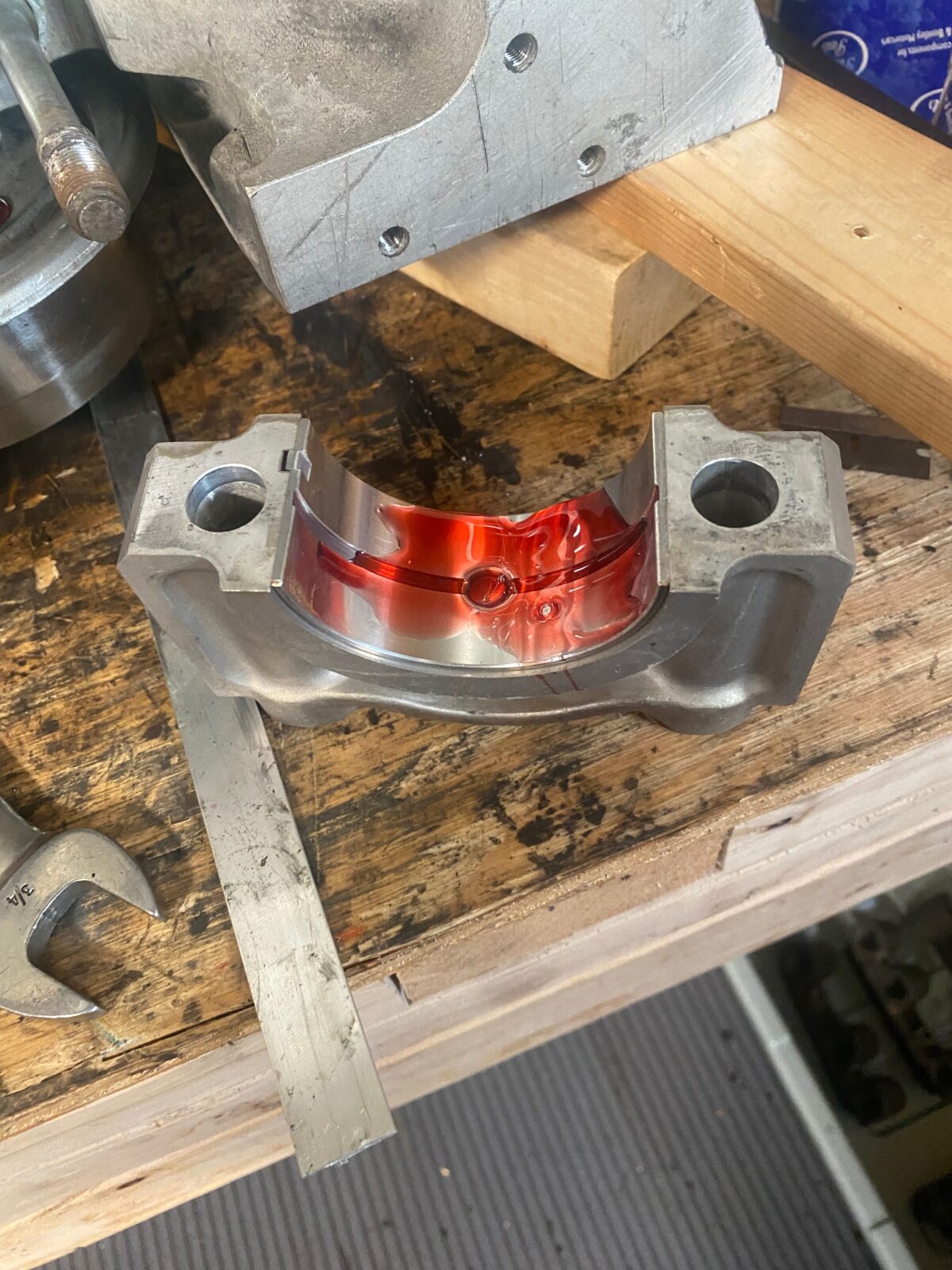
Inserting the thrust bearings in the center main.
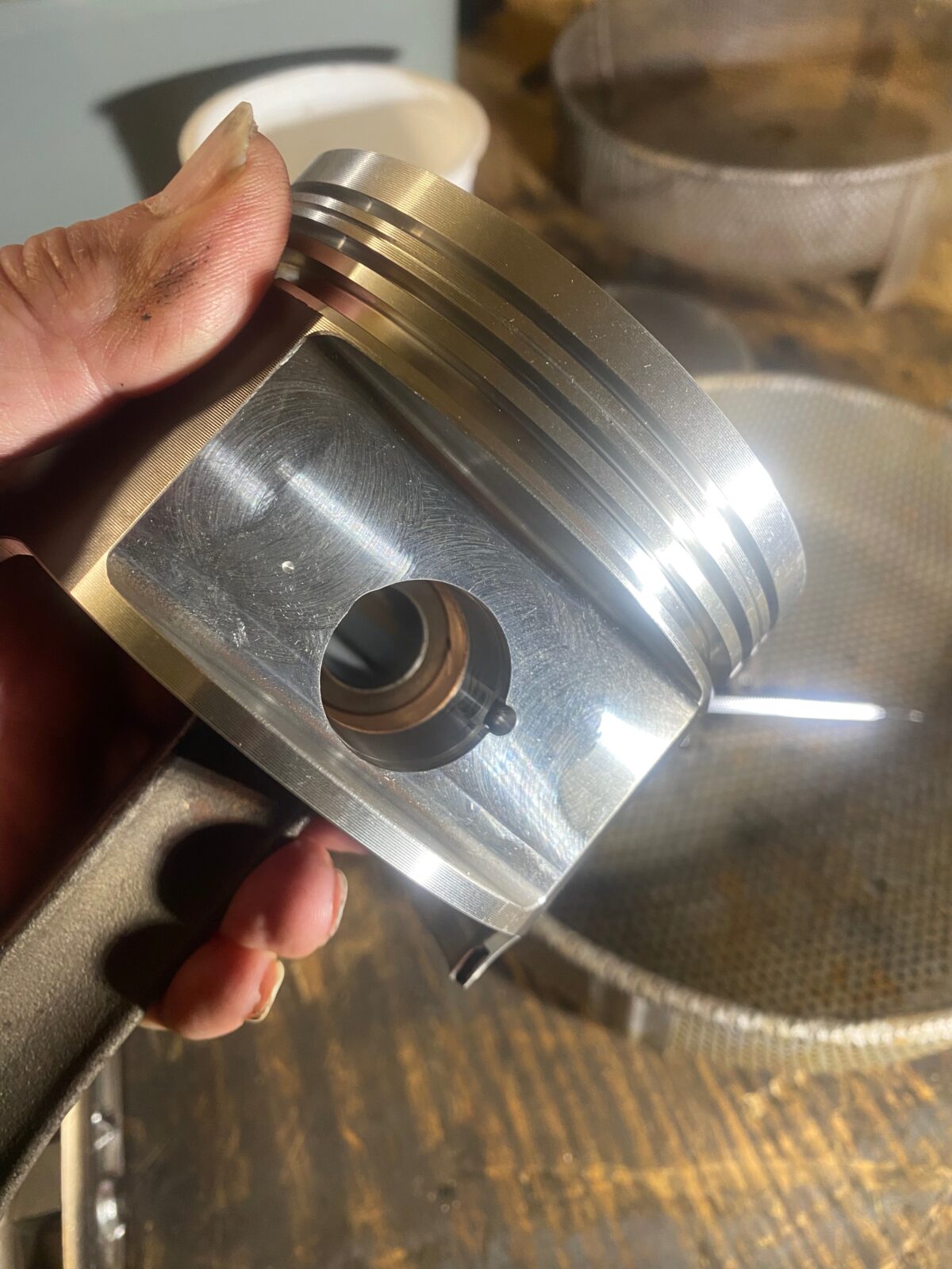
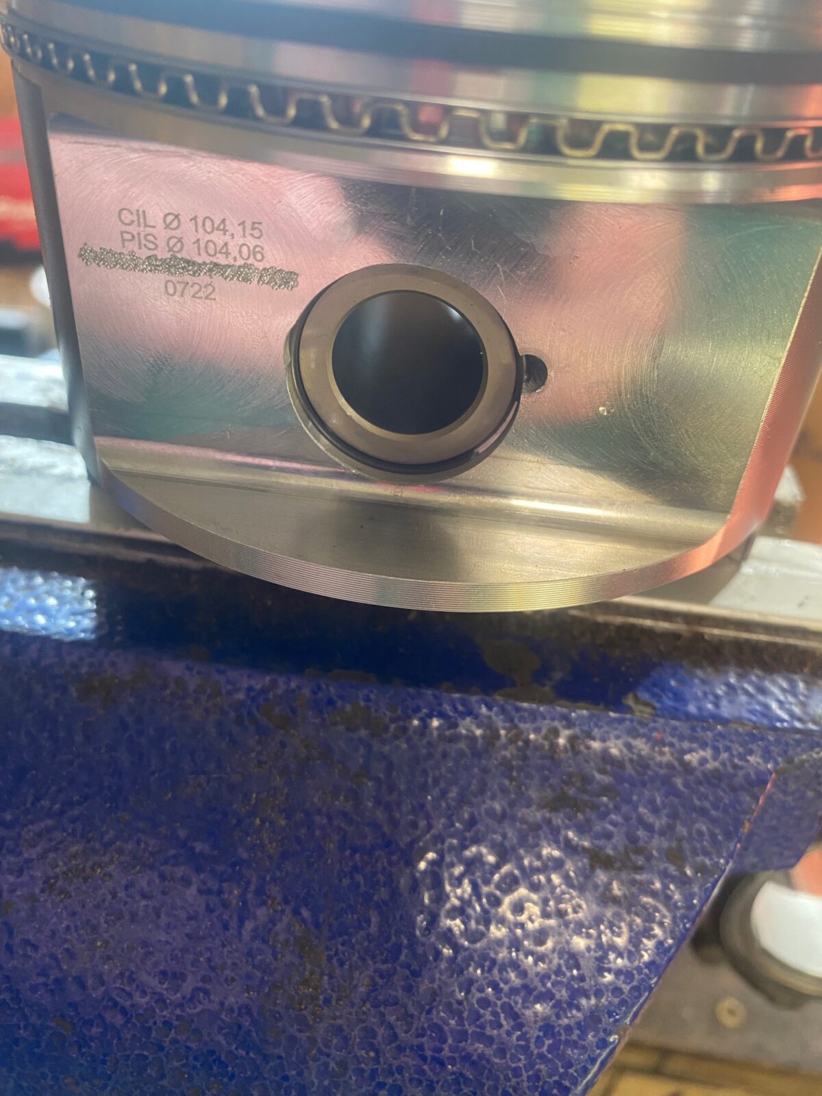
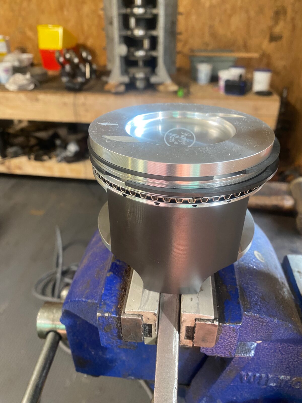
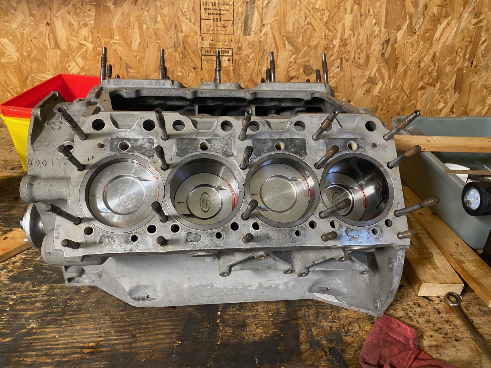
Pistons, pins and rings
Fitting the pistons
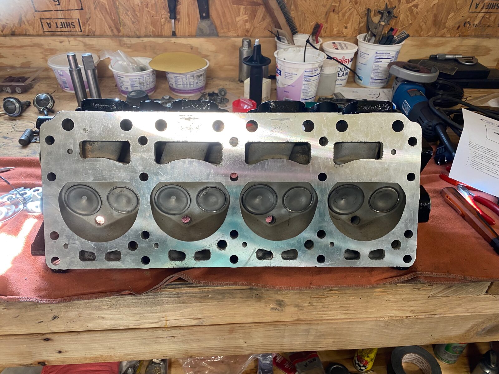
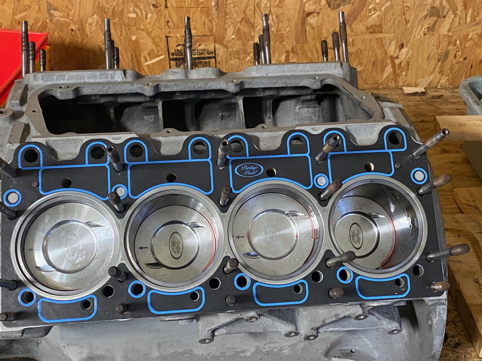
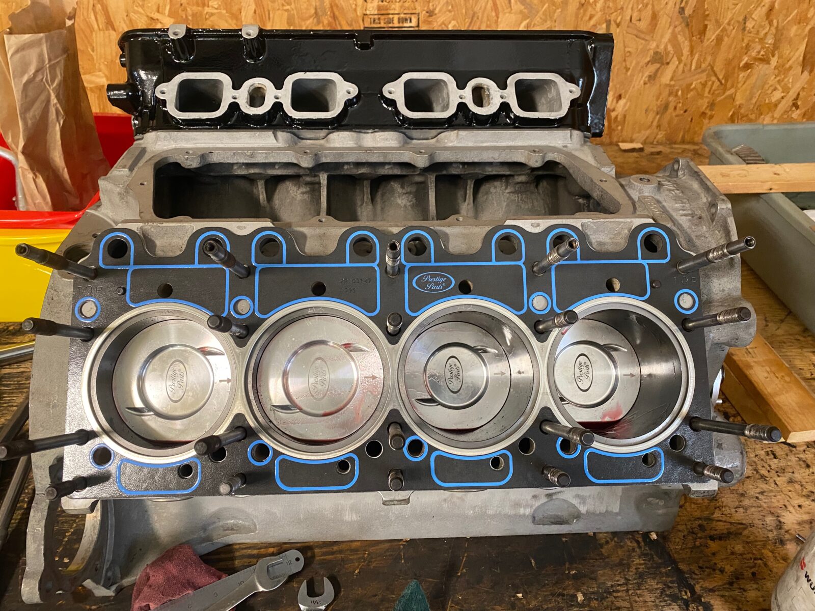
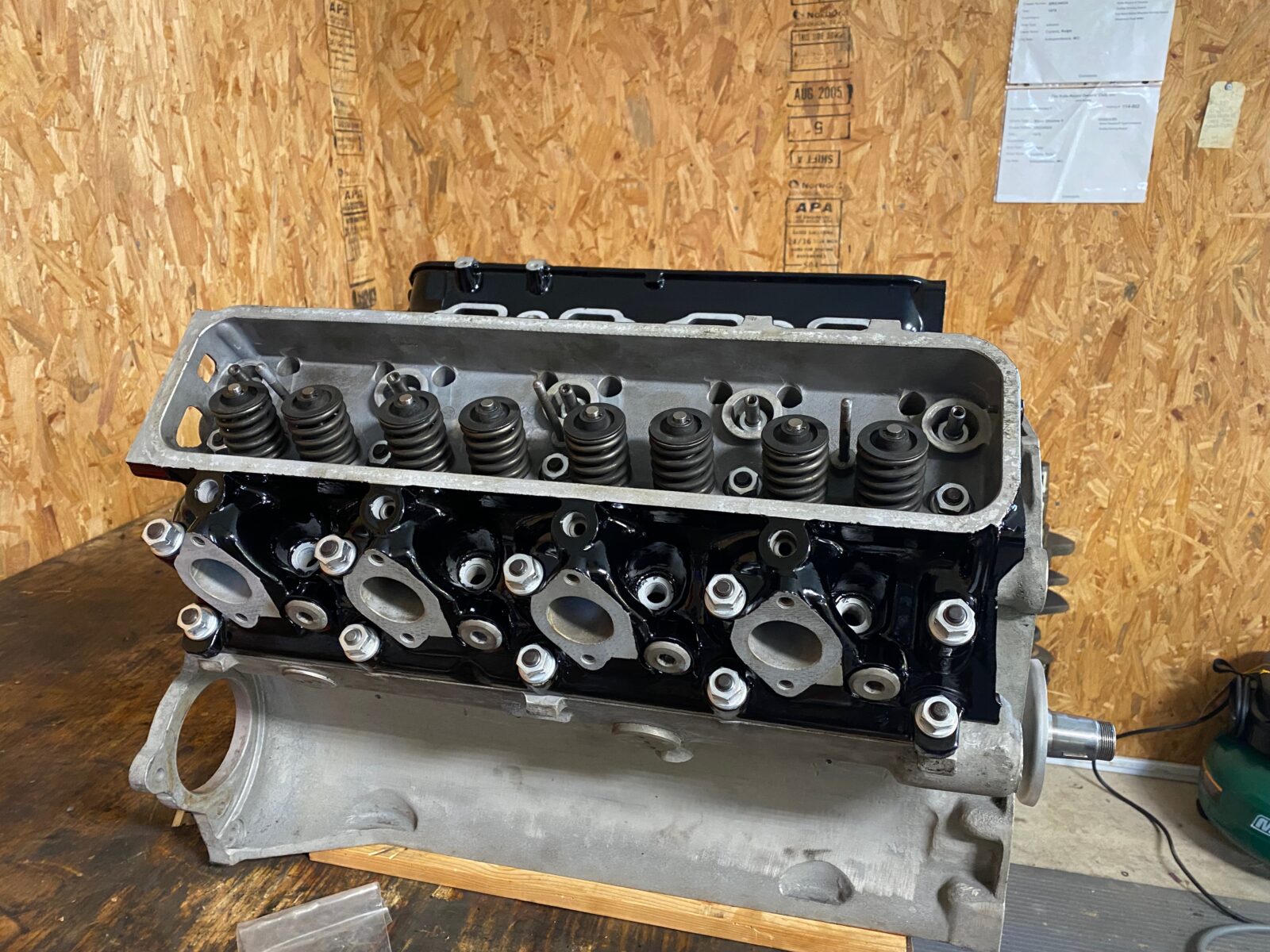
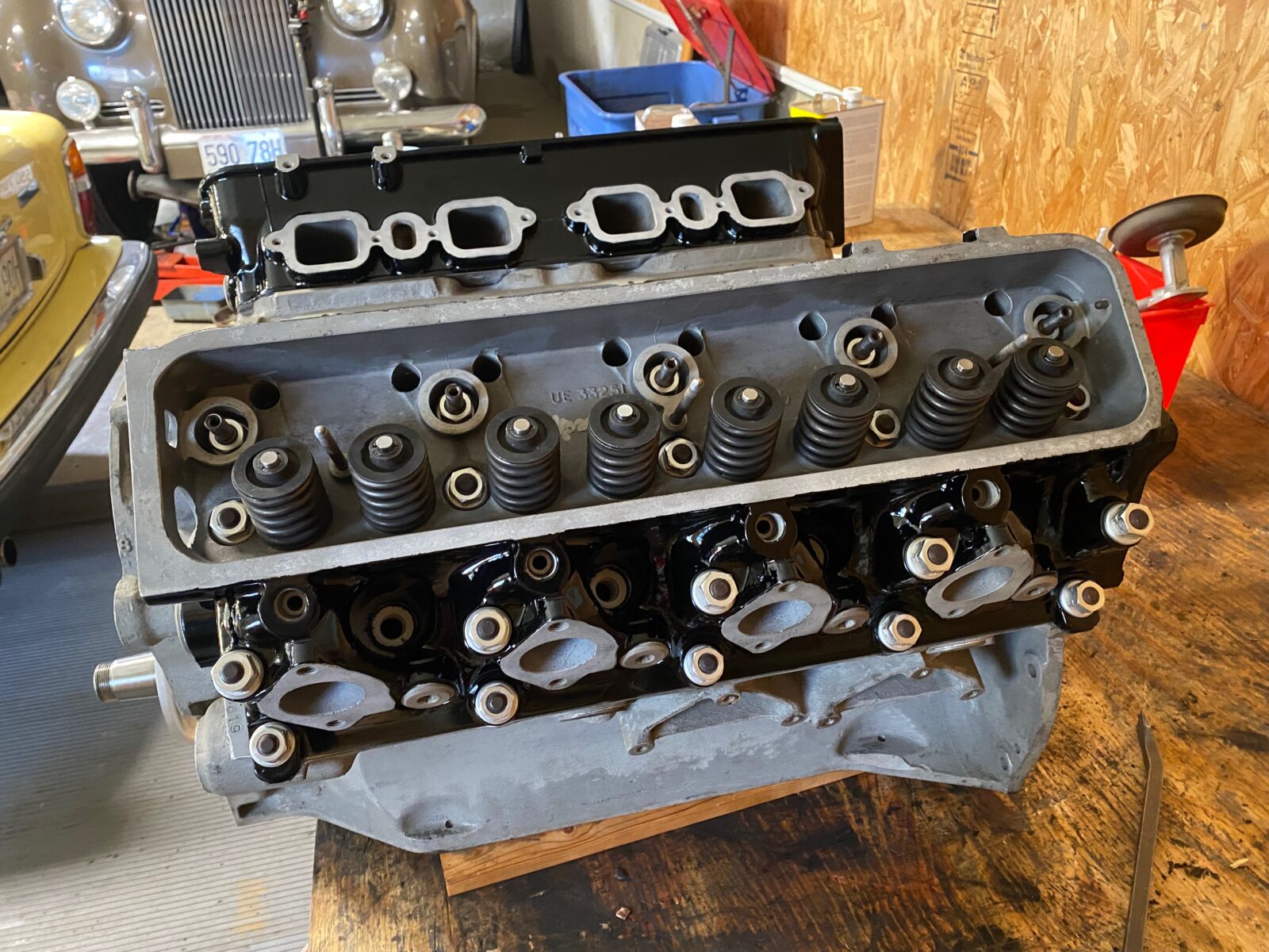
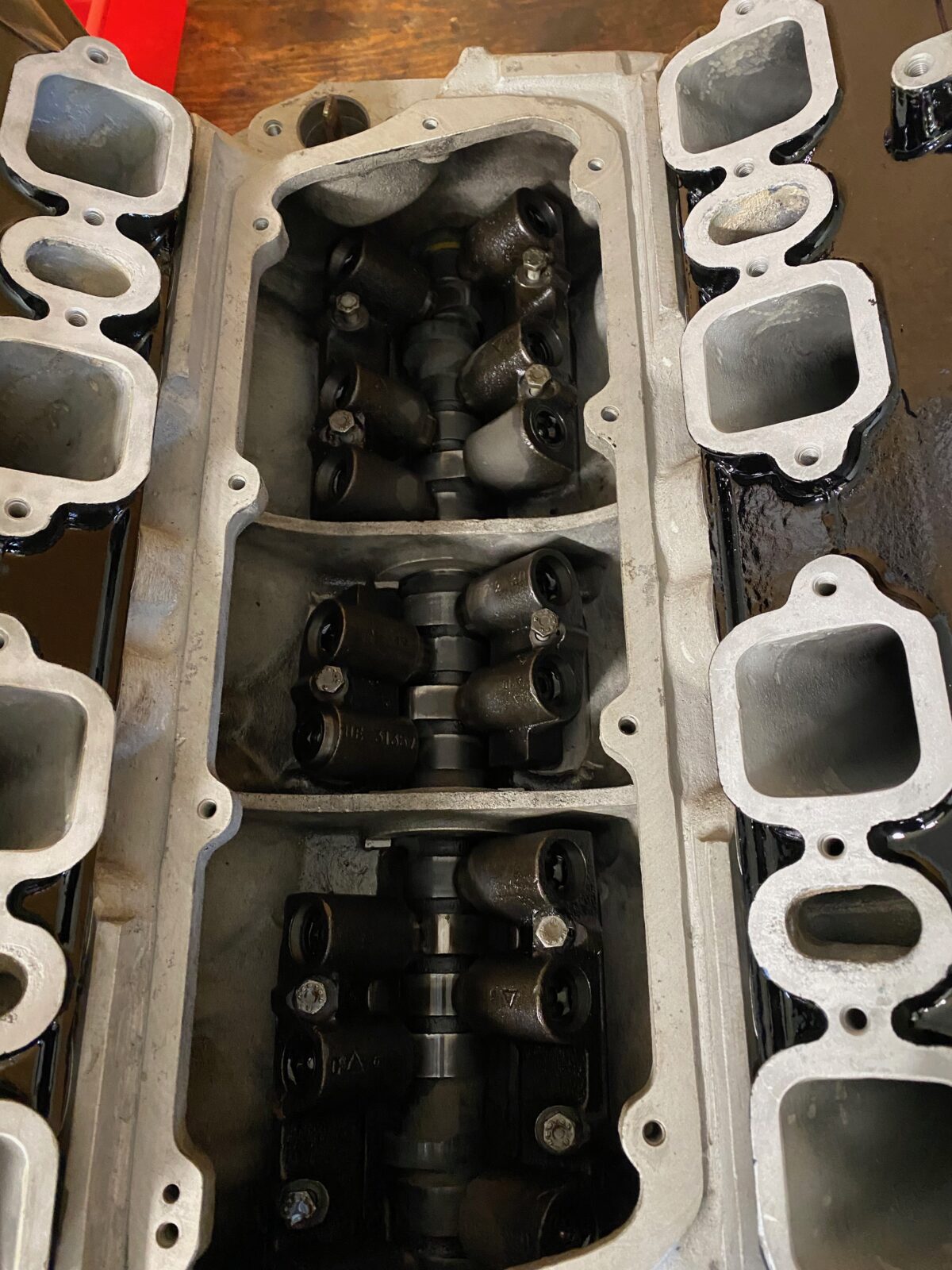
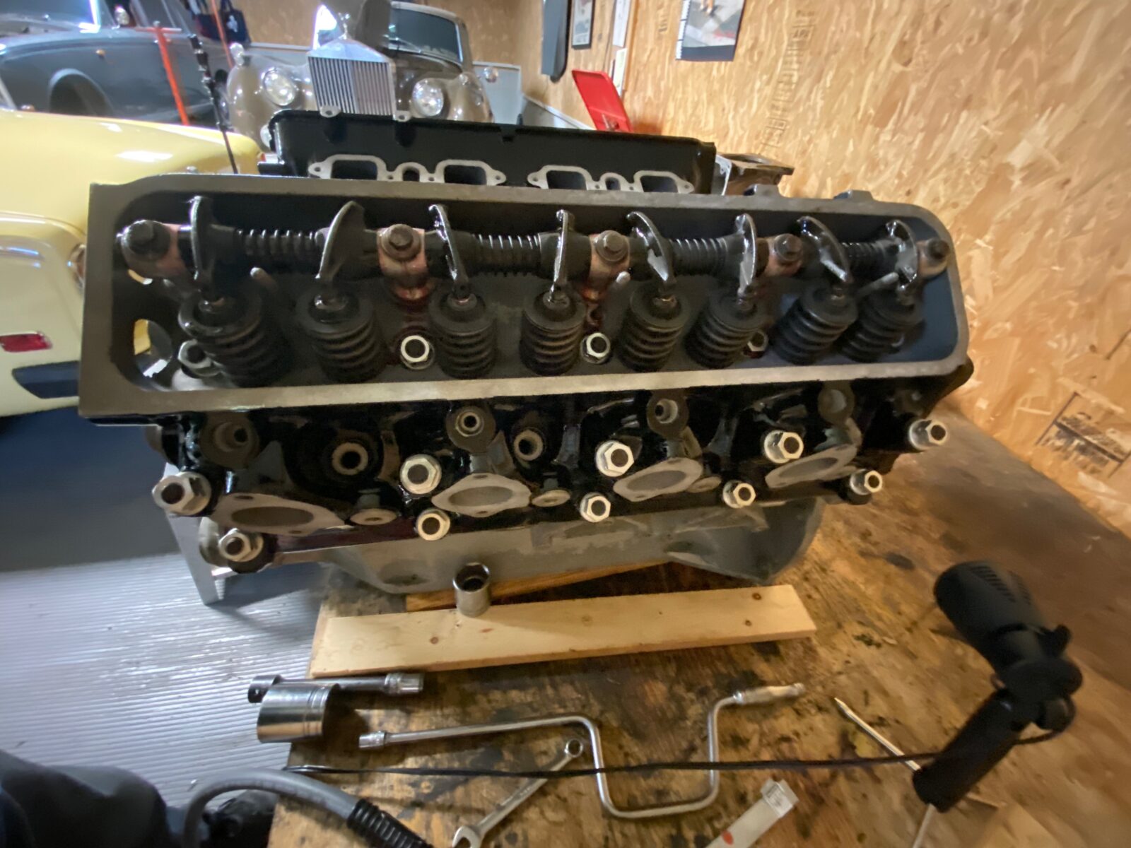
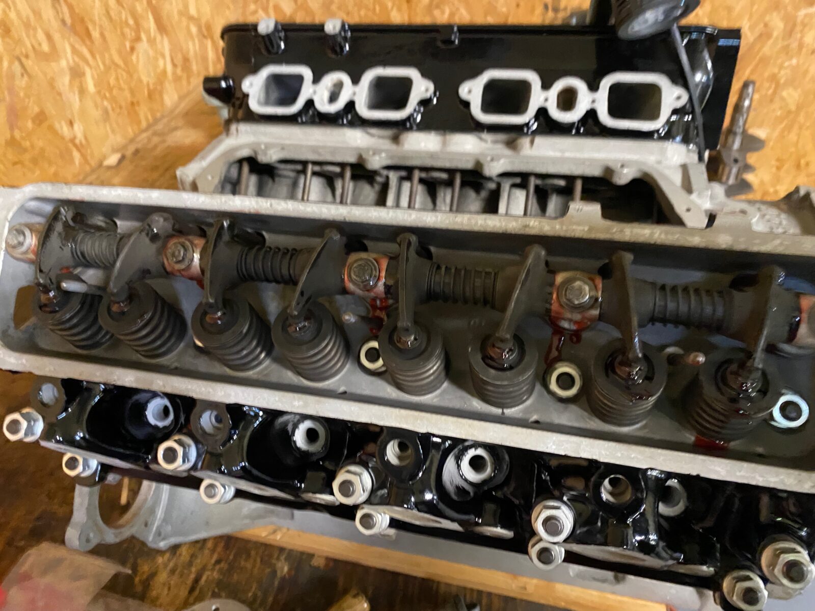
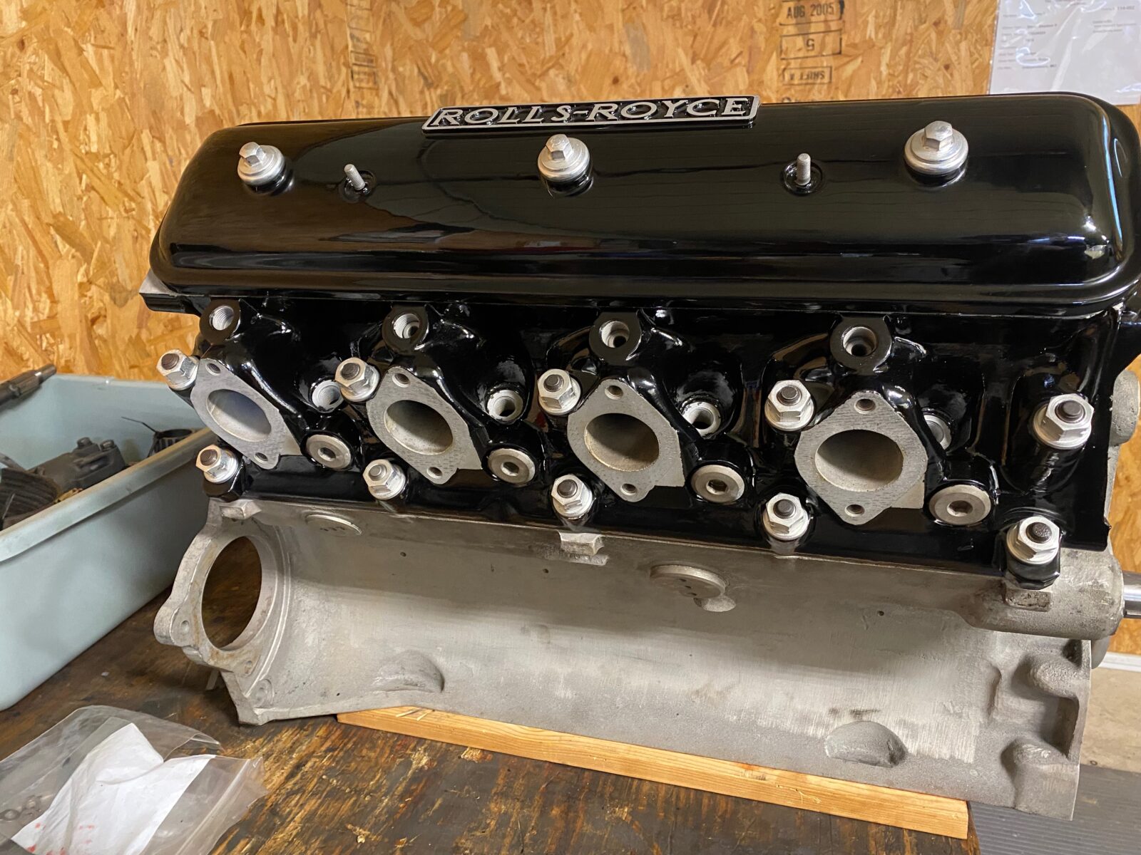
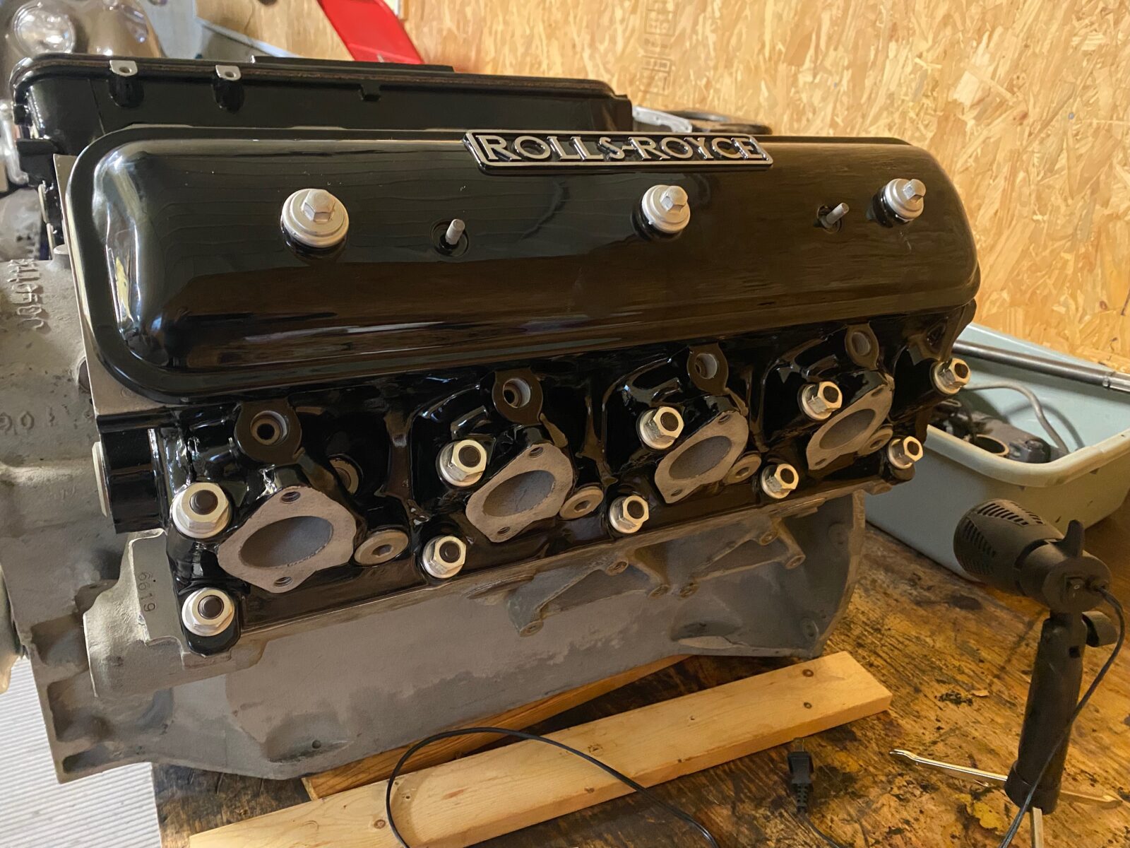
Cylinder head installation
Be sure to check the lineup of the gasket to the holes. Gaskets are marked with “Top” so pay attention. Click on photos for full view.
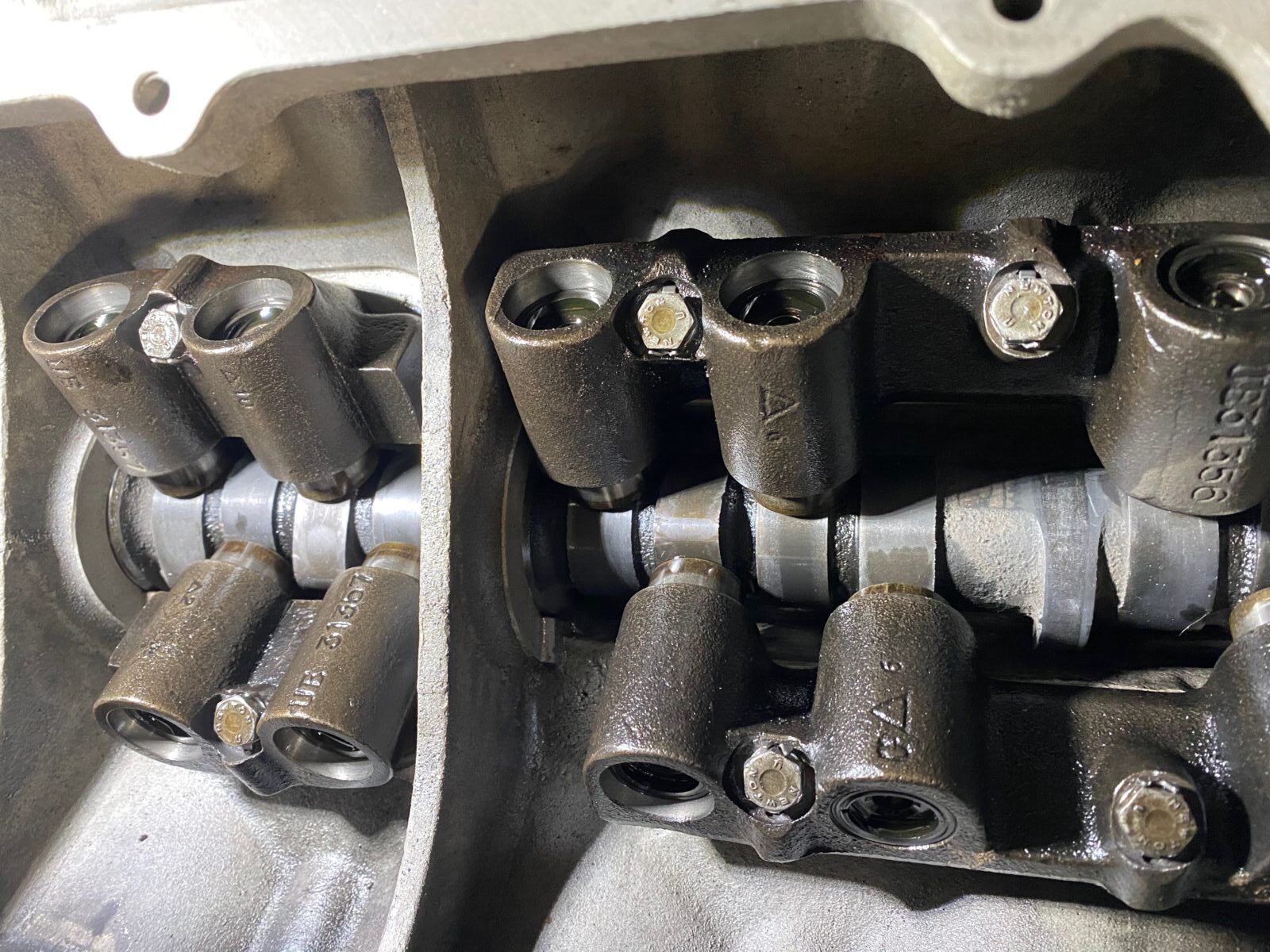
Camshaft installation
Click photos for full view.
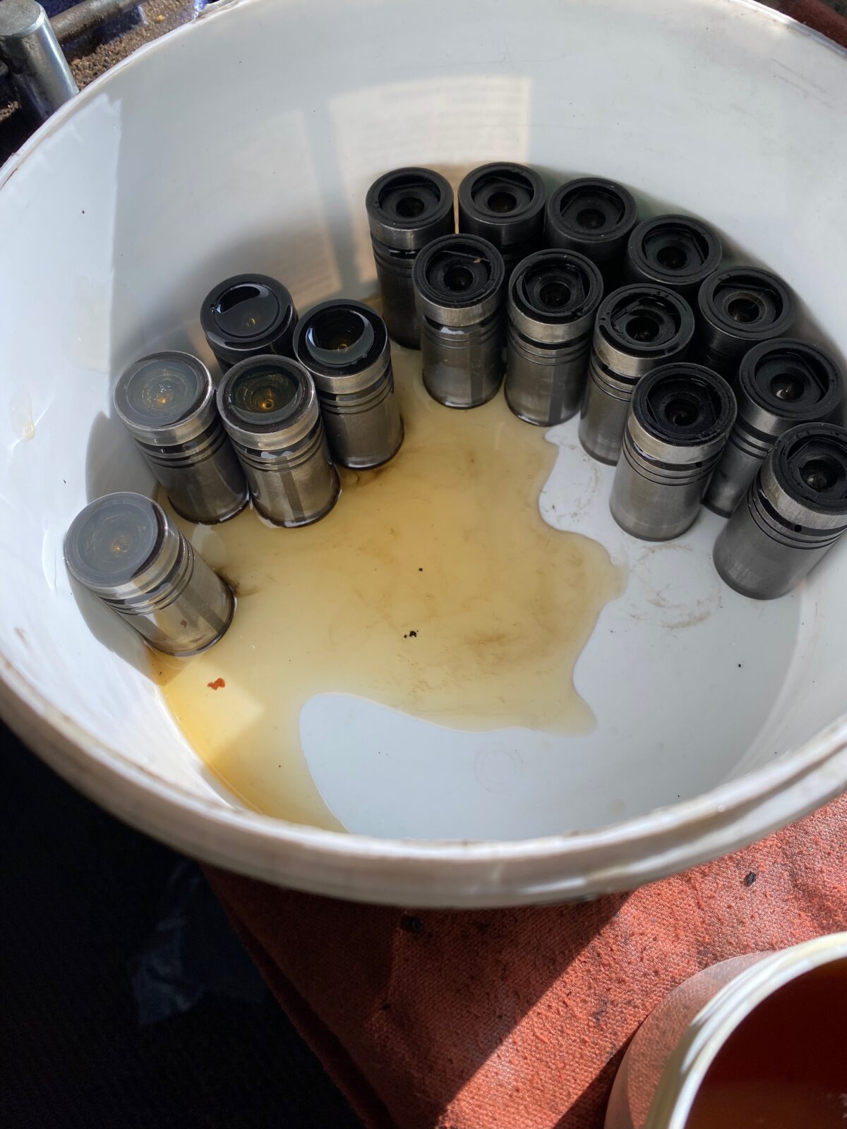
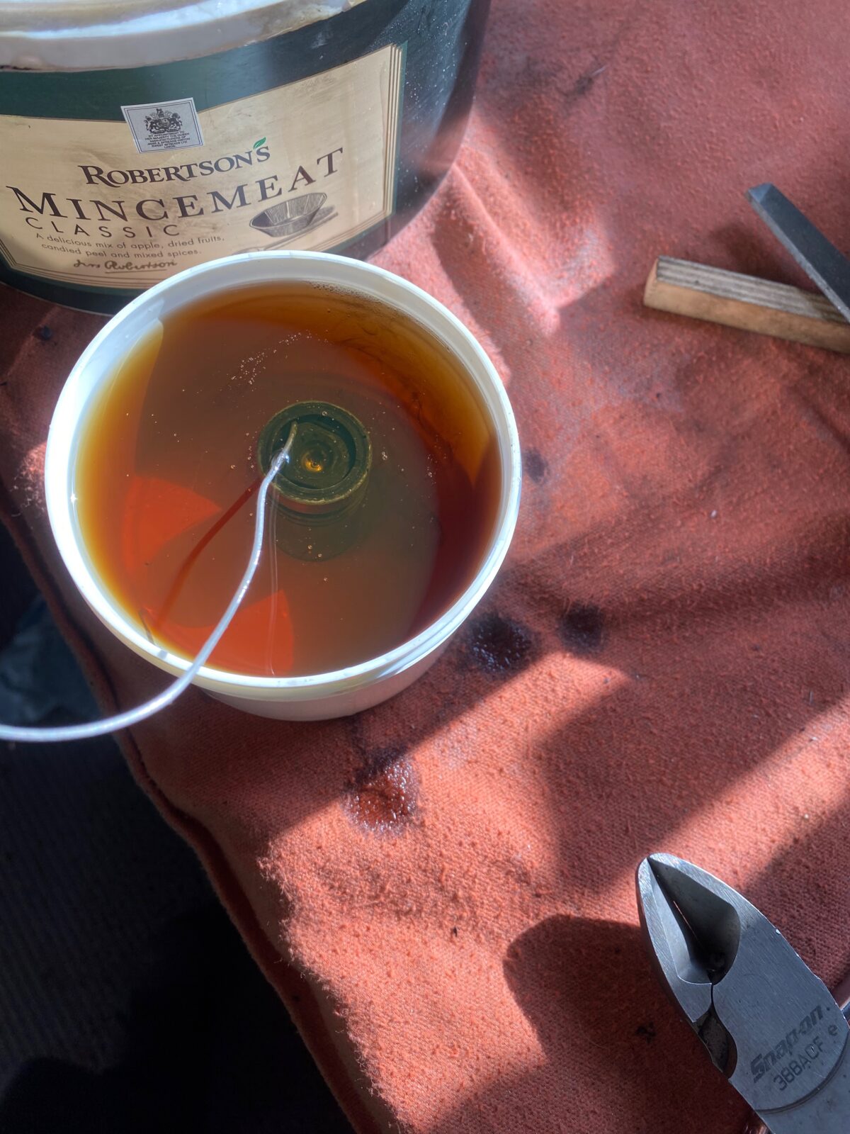
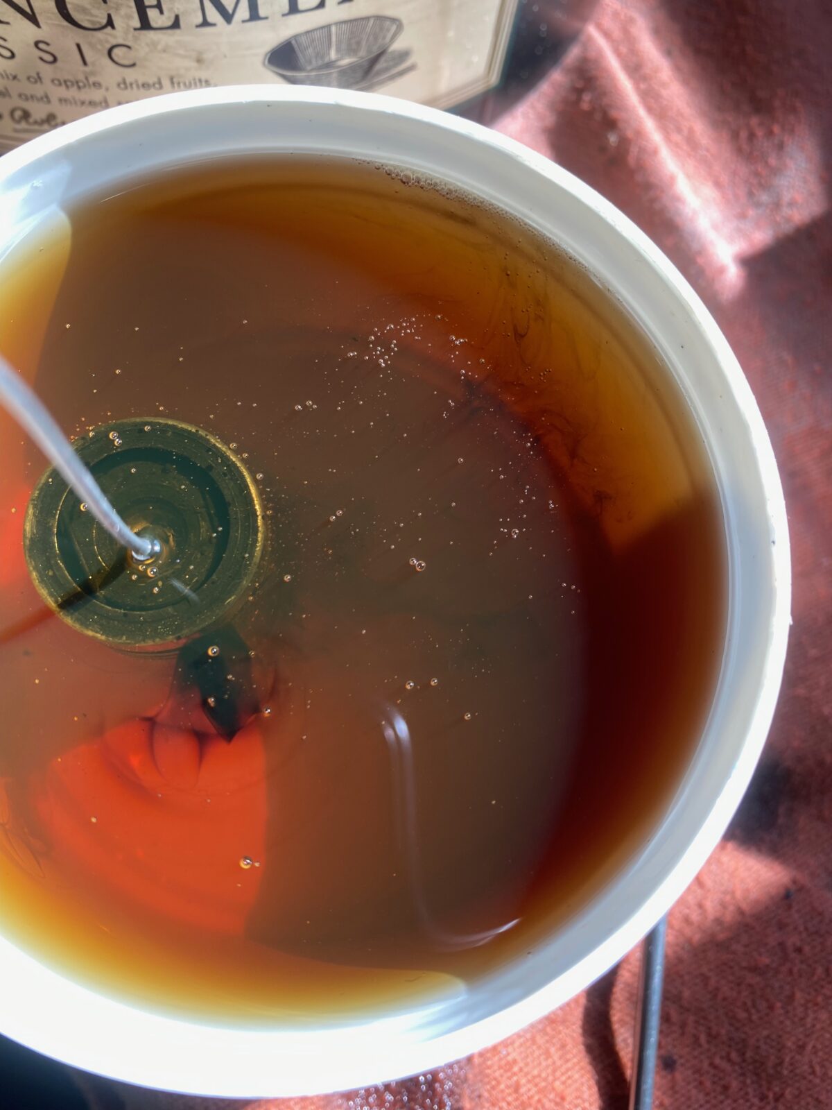
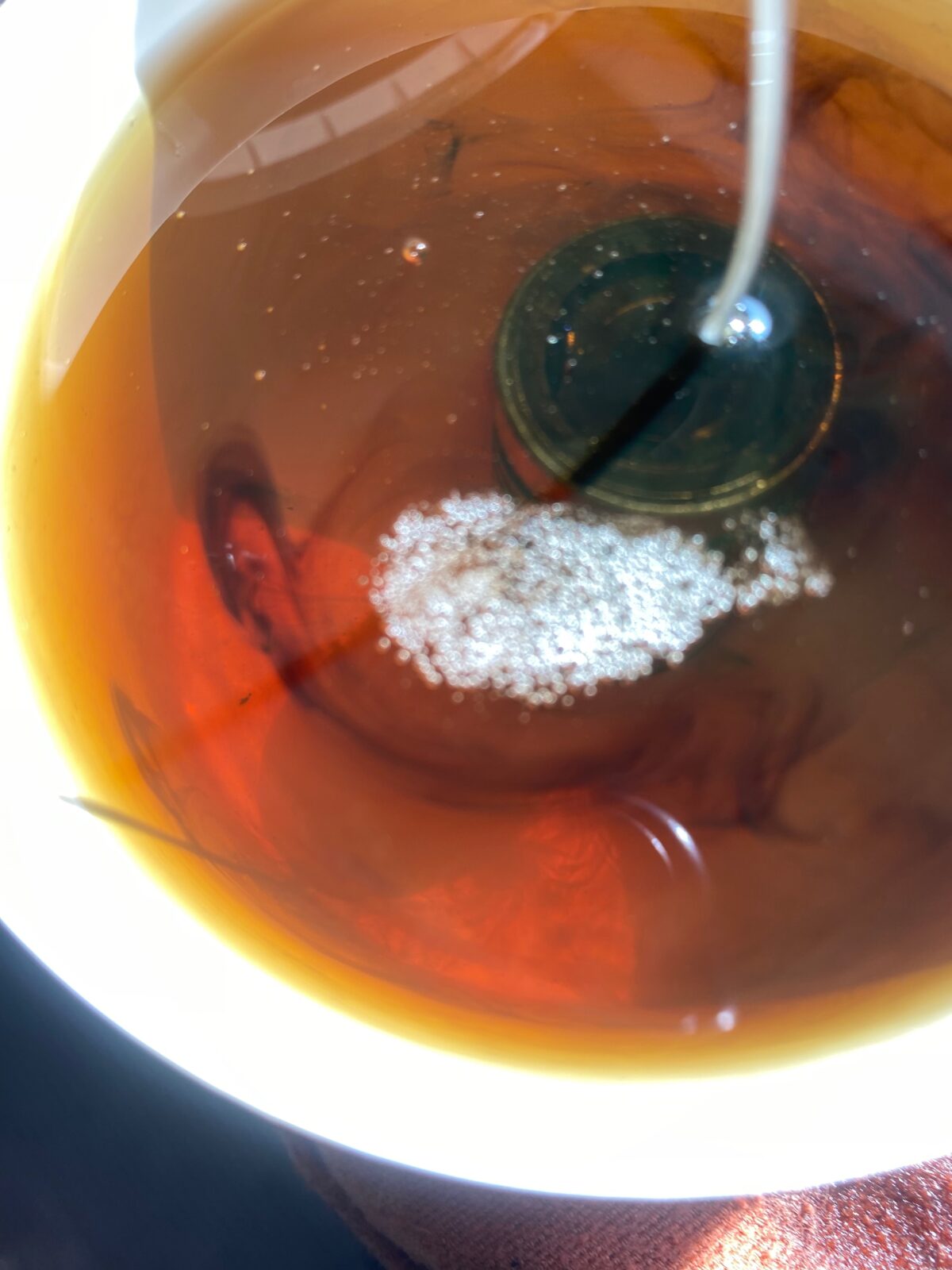
Hydraulic Lifter Bleeding & Installation
To bleed the hydraulic lifters, take a paper clip and straighten it out. Push it through the center hole with the hydraulic lifter IMMERSED IN OIL, you then push the center of the lifter down with a small screwdriver to expel the air and fill the hydraulic lifter with oil.